Lecture
Color television systems are built in such a way that they are compatible with the black-and-white television systems that appeared earlier. This means that color television signals are transmitted on the same channels and in the same frequency band as black-and-white television. The main characteristics of black and white television correspond to the same indicators of color television.
The transmission of color images in photography, cinema, and television is based on the theory of three-component color vision. According to this theory, the sensation of any color can be obtained by mixing in a certain proportion three signals with different wavelengths (three different colors). As the reference signals (colors) choose those which, when mixing two colors in any proportions, do not give the sensation of the third color. International agreements recommend using monochromatic optical signals with wavelengths corresponding to red (λ R = 700 nm), green (λ G = 546.1 nm) and blue (λ В = 435.8 nm) colors as reference signals. The choice of such waves is determined both by their linear independence and the availability of formation on the existing equipment.
To obtain signals of primary colors in opto-electronic converters of an image into an electrical signal, the luminous flux is divided into three components with a certain spectral composition using color separation mirrors or light filters. In the inverse transformation of each of the signals, one of the three color separation images is obtained. The spatial combination of these monochromatic images restores the color image of the object.
The compatibility of black-and-white and color television systems is based on the fact that a color television system should use a signal that would give a black-and-white image on a black and white TV screen. This means that in color television systems, a luminance signal should be used as a reference, and additional signals would provide color transmission.
The brightness signal E Y (white color) can be obtained by mixing the signals of the three primary colors in certain proportions
E Y = aЕ R + bЕ G + cЕ B , (9.1)
where Е R , Е G and Е В are the reference signals of the primary colors, respectively, of red, green and blue; a, b, c are coefficients determined by the sensitivity of the eye to the corresponding colors.During the formation of white color, it is usually assumed that the sources of primary colors provide the same intensity of the main signals Е R = Е G = Е В. In various color television standards, the coefficients a, b, c take different values, for example, in the domestic standard they are assumed to be: a = 0.299, b = 0.587, c = 0.114.
The optoelectronic converter can be represented as three photoelectric converters that simultaneously form signals of three primary colors for each element of the decomposition. Structurally, the three transducers, forming the signals of red, green and blue, are combined into a single node. The next time point, the signals of the primary colors of the neighboring decomposition element, etc. are transmitted. A diagram of the formation of the brightness signal of the three brightness color signals is shown in Figure 9.6, a. The choice of resistors' resistance ensures the necessary transmission coefficient of each of the resistive dividers in accordance with expression (9.1).
For the transmission of color images, in addition to the luminance signal, they transmit chrominance signals. To receive a signal about color, it is enough to transmit only two color signals. The signal of the third color can be restored in the receiver from the luminance signal and the signals of the two other primary colors. This method has some redundancy, since the signal of each color also contains information about the brightness.
In color television systems, instead of two-color signals, it is more effective to transmit so-called color difference signals, for example:
E RY = E R - E Y , (9.2)
E BY = E B - E Y. (9.3)
These signals do not carry information about the brightness and when transmitting areas of white or gray color difference signals are equal to zero (for Е R = Е G = Е В ). Formation of the color difference signal can be provided by the impedance matrix shown in Figure 9.6, b.
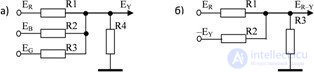
Fig. 9.6 Formation of color television signals: a) luminance signal; b) color difference signal
When transmitting the E Y luminance signals and two color difference signals, to the distortions of tones of which the eye is least sensitive: E RY and E BY , signals of all primary colors can be received at the receiver:
E R = E Y + (E R - E Y ), (9.4)
E B = E Y + (E B - E Y ). (9.5)
E G = [Е Y - (aЕ R + cЕ B )] / b, (9.6)
where the coefficients a, b, c are selected in accordance with expression (9.1).
Taking into account the properties of vision, the spectrum of color difference signals can use a smaller frequency band than the spectrum of a luminance signal. With a decrease in the angular dimensions of the parts under consideration, less than 10 ′, the vision from color changes to monochromatic. Without a noticeable deterioration in the quality of the color image, the band of the color difference signal can be reduced to 1.5 ... 2.0 MHz, with the smallest details of the image being reproduced in black and white.
In the color television system, in general, additional measures are required to transmit chroma signals within the standard black and white television channel. In various standards of broadcast television, the problem of spectrum multiplexing is solved in various ways. Currently, the most widespread following color television systems: NTSC (USA), PAL (Germany), SECAM (France). Russia uses the French standard for color television broadcasting. Modern generations of television receivers allow to receive color transmissions of various standards.
Receivers of color television have the same image channels (brightness) and sound, as with black-and-white televisions. Additionally, for processing color television signals, a receiver has a decoder (chrominance unit) that provides decoding of received signals. The resulting decoding signals are used to obtain a color image on the screen of the electron-optical converter.
One of the directions of development of television is the improvement of systems that provide high definition images. In high-definition television systems, an image is formed by an increased number of decomposition elements, the most preferred frame format for users (ratio of screen width to its height) is 16: 9 (standard broadcast television uses a ratio of 4: 3).
The most promising direction of television broadcasting, perhaps, is digital television. Digital signal processing technologies are successfully applied in all areas of communication. The peculiarity of television signals, which until recently had slowed down the introduction of digital technologies, lies in their relatively wide spectrum (the luminance signal occupies the 6 MHz band, the chrominance signals - 1.5 ... 2.0 MHz). The direct conversion of such broadband signals to digital format leads to a significant expansion of the spectrum. Such an “exchange” of improving the quality of signals by expanding the required frequency band occupied by a signal is characteristic of digital communication systems.
Calculations show that a channel with a bandwidth greater than 100 MHz is required to transmit a digitized television signal. Therefore, the most important task in the development of digital television systems is to solve the problem of data compression in video signal processing. Modern information compression systems can thus encode a video image that the width of the spectrum of the digitized signal becomes comparable or even less than the width of the spectrum of an analog television signal.
In addition, digital methods of transmitting and distributing signals allow you to organize an interactive (two-way) exchange of information with the user of television broadcast programs. In this case, a narrowband feedback channel is organized, allowing you to select and receive additional digital television services.
§ Transfer color image
The basis of color television based on the principle of splitting the color energy from the image element into three component colors - red, blue and green. In accordance with the wave theory of color, red has a wavelength of 687 nm, green is 527 nm, and blue is 485 nm. For pure red, blue and green colors, a system of dichroic mirrors is used (these are special composite mirrors that allow you to transmit or reflect a certain wave of light).
In a video camera, two dichroic mirrors are used, which are mutually perpendicular. In this case, the first mirror reflects the red color and skips the green and blue. The second mirror reflects blue and skips the remaining green. To obtain electrical signals of analog or digital form ER, EG and EB (R - red - red, G - green - green, B - blue - blue) reflected colors are fed to the receiving and transmitting tubes, which form the electrical signals of the colors of each image element.
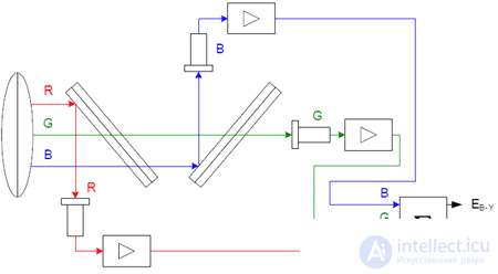
Fig. 5 Scheme for obtaining electrical signals of a color image.
EY - luminance signal. The received signals ensure the formation of the CPTS. The brightness signal EY is transmitted to the main image carrier. This signal is the main one, which provides the combination of various television systems. The television receiver receives a green signal EG, which is not transmitted, but is formed by the following
formula:
EY = 0.3 ER + 0.59 EG + 0.11 EB.
When transmitting a color image, regardless of the system, the CPTS spectrum will look like this.
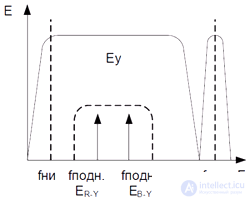
Fig. 6 Spectrum CPTS.

Comments
To leave a comment
Devices for the reception and processing of radio signals, Transmission, reception and processing of signals
Terms: Devices for the reception and processing of radio signals, Transmission, reception and processing of signals