Lecture
In developing the receiver’s structural scheme, we determined that from the amplifier of the second intermediate frequency, in addition to providing the necessary selectivity in the adjacent channel, which is implemented by a concentrated selection filter, it is necessary to ensure maximum gain of the received signal power. It is the amplifier of the second intermediate frequency that brings the signal level to the value necessary for the normal operation of the FM demodulator, thereby ensuring the necessary sensitivity of the radio receiver. At the same time, the level of the received signal can be quite large when working at a short distance from the transmitter. This means that the gain of the intermediate frequency amplifier should vary from maximum to minimum depending on the level of the input signal. This means that the gain of the amplifier of the second intermediate frequency should be changed by the automatic gain control system (AGC).
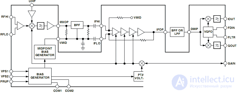
Currently, microcircuits are implemented that implement a transistor mixer, UPCH and a single-chip detector. As an example of such a chip, you can call the AD607 chip from Analog devises. The block diagram of the IF amplifier assembled on the AD607 microcircuit is shown in Figure 1.

Figure 1. Structural diagram of the IF amplifier assembled on the AD607 microcircuit
In this diagram, three independent blocks are clearly visible. The intermediate frequency amplifier, located between the mixer and the IQ demodulator, has a gain of 70 dB. Together with the possibility of changing the gain of the mixer by 20 dB, the gain adjustment of the AD607 chip reaches 90 dB.
Comments
To leave a comment
Devices for the reception and processing of radio signals, Transmission, reception and processing of signals
Terms: Devices for the reception and processing of radio signals, Transmission, reception and processing of signals