Lecture
When developing any block of a radio electronic device, it is important to fulfill the requirements imposed on it at the stage of developing a structural scheme. When developing a block diagram of a radio receiver, we determined that the amplifier of the second intermediate frequency is required to provide the maximum gain of the received signal power. It is the amplifier of the second intermediate frequency that brings the signal level to the value necessary for the normal operation of the FM demodulator, thereby ensuring the necessary sensitivity of the radio receiver. At the same time, the level of the received signal can be quite large when working at a short distance from the transmitter.
When working with angular (frequency or phase) modulation types, such as frequency modulation, GMSK, useful information is embedded in a change in frequency or phase, so after selecting the frequency range of the useful signal, in some cases you can lose information about the amplitude of the original signal. Naturally, the spectrum of the received signal will expand, but since the suppression of out-of-band interference is already completed, it is possible to prevent the spread of the signal spectrum at this stage of reception.
The fact that we have allowed the possibility of losing information about the amplitude of the received useful signal allows us to use amplifiers that limit its amplitude - limiting amplifiers. This greatly simplifies the intermediate frequency amplifier circuit, since no automatic voltage control (AGC) circuit is required.
Currently, there are a lot of chips implemented according to this scheme. As an example of a domestic intermediate-frequency amplifier chip with an integrated amplitude limiter, you can call the K174XA10 chip. This chip is designed for the implementation of single-chip broadcast receivers. Such chips are also used to implement the intermediate frequency paths of professional radio stations. These are such chips as SA607, SA616, SA627, SA636. They are based on differential amplifiers. These chips differ slightly from each other. Basically dimensions and input / output impedance of amplifiers. The SA627 has a built-in noise suppressor. An example of a circuit diagram of a second intermediate frequency path implemented on an SA616 chip manufactured by Philips Semicondactors is shown in Figure 1.
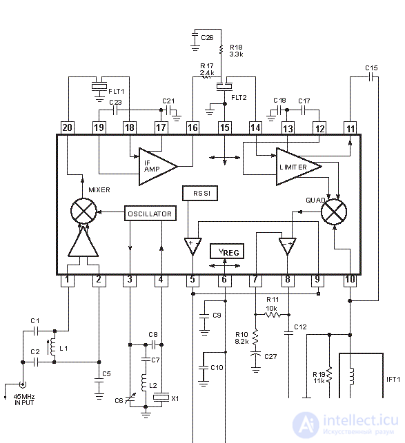
Figure 1 Schematic diagram of the IF amplifier assembled on an SA616 microcircuit
This chip contains a transistor mixer (MIXER), an intermediate frequency amplifier (IF AMP), a limiting amplifier (LIMITER) and a frequency detector (QUAD) in one package. The gain of the intermediate frequency amplifier IF in this chip is 44 dB. The gain of the LIMITER amplifier-limiter in the SA616 chip is 58 dB. The overall gain of the IC reaches 100 dB. This is quite enough for the realization of the ultimate sensitivity of frequency modulation receivers.
Unfortunately, the mixer node has a rather low IP3 value of –9 dBm. The main selectivity of the receiver on the adjacent channel is carried out after this node, therefore, in order to ensure acceptable parameters for intermodulation, it is desirable to implement the mixer on a separate chip with higher values of this parameter.
The use of narrow-band quartz filters of the first intermediate frequency (usually 45 MHz) can be mentioned as a circuit solution that allows the use of a frequency converter integrated into the chip SA616 (SA627, SA636). In this case, the level of the second and fourth adjacent channels (the most dangerous from the point of view of intermodulation distortion) will be attenuated sufficiently so that these distortions can be pre-scored.
The input voltage of the intermediate frequency amplifier is fed through a ceramic filter of the main selectivity FLT1. A filter similar to SFPKA455KF4A-R1 from Murata is usually used. Its average frequency is 455 MHz. Such a filter is capable of attenuating the signal power of a neighboring channel by 30 dB, therefore, two filters are usually included in the second intermediate frequency path. But the filters can not be loaded on each other, so the second filter is placed at the output of the intermediate frequency amplifier IF. Since the signal of the adjacent channel is already suppressed by 30 dB, the gain of the input signal power by 40 dB does not lead to any unpleasant consequences.
When connecting filters to other circuit elements, it is very important to match their input and output impedances. In filters, the mismatch of the input and output of the filter with respect to resistance can lead to a sharp change in the amplitude-frequency characteristic (frequency response breakdown). The input impedance of the intermediate frequency amplifiers IF and the LIMITER limiter amplifier in the SA616 chip is 1.5 kΩ, so no additional matching with the SFPKA455KF4A-R1 filter is required (its input and output resistance is 1.5 kΩ).
The work of the next part of the chip SA616, which performs demodulation of the frequency-modulated signal QUAD, we will look at later in an article on frequency demodulators. At the end of this article I would like to give the circuit of the second intermediate frequency path, made according to Russian GOST. Such a scheme is shown in Figure 2.
Figure 2 Schematic diagram of the path of the second intermediate frequency, assembled on the chip SA616

Comments
To leave a comment
Devices for the reception and processing of radio signals, Transmission, reception and processing of signals
Terms: Devices for the reception and processing of radio signals, Transmission, reception and processing of signals