Lecture
At the output of the balanced mixer, the voltage of the local oscillator is suppressed, but the voltage of the received operating signal is present. As discussed when considering the principles of operation of a superheterodyne receiver, the output of the ideal multiplier of these components should not be in principle. Reduce the level of the radio signal at the output of the frequency converter allows the ring mixer circuit (frequency converter). This circuit is often called a double balanced mixer. A schematic diagram of a diode ring mixer is shown in Figure 1.
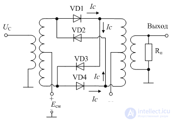
Figure 1. Diagram of a diode ring mixer (frequency converter)
The suppression of the input signal at the output of the ring mixer (frequency converter) is performed by subtracting the currents of the balanced mixer assembled on the VD1, VD4 diodes and the currents of the balanced mixer assembled on the VD2, VD3 diodes.
The spectrum of the signal at the output of a balanced ring mixer (frequency converter) is shown in Figure 2.

Figure 2. The signal spectrum at the output of a balanced ring mixer (frequency converter)
Note that the spectrum of the signal at the output of the ring mixer (frequency converter) is already similar to the spectrum of an ideal multiplier. Insufficiently suppressed components of the output spectrum should be suppressed by bandpass filters at the input and output of the mixer.
At the output of the circuit of the ring mixer (frequency converter), not only the signal present at the input of the frequency converter is suppressed, but also all the components formed by the odd powers of the approximation polynomial of the steepness of the nonlinear elements used in the mixer. The process of suppressing the input signal at the output of the ring mixer (frequency converter) is illustrated in Figure 3.

Figure 3. Timing diagram of the output voltage of the ring mixer (frequency converter)
This figure considers the situation when the frequencies of the received signal and the local oscillator are equal. The timing diagram of the output current resembles the timing diagram of a rectified signal. As a result, the even half-waves of the received signal suppress the odd ones. This leads to the fact that all the odd harmonics of the output spectrum are suppressed. The spectrum of the output signal mainly contains even-harmonic components:
 (one)
(one)
If the volt-ampere characteristic of the nonlinear element is approximated by a quadratic function (a second-order polynomial), then we obtain a converter as close as possible to the ideal multiplier. Approximation of the shape of the current-voltage characteristics of the mixing diodes to the quadratic polynomial can be obtained by appropriate selection of the bulk resistance of the semiconductor.
Currently, ring diode mixers (frequency converters) are made in the form of ready-made integrated circuits. In this case, the input and output impedance is equal to 50 Ohms. The input impedance of the local oscillator is also made equal to 50 Ohms. The integral design of the ring mixer (frequency converters) allows to achieve a high degree of symmetry of the mixer arms, which allows to obtain fairly good characteristics of the suppression of the local oscillator signals in the radio and intermediate frequency circuits. As an example of such ring mixers (frequency converters), mixers manufactured by Mini-Circuits can be cited. The parameters of some of them are given in table 1.
Table 1 Parameters of ring mixers (frequency converters)
| Mixer Type | LO level (dBm) | Single Compression Point (dBm) | IP3 (dBm) | Frequency range of the local oscillator and radio frequency (MHz) | Intermediate Frequency Range (MHz) | Conversion loss (dB) | Isolation between radio frequency and local oscillator inputs (dB) | Isolation between intermediate frequency and local oscillator inputs (dB) |
|---|---|---|---|---|---|---|---|---|
| ADE-1L | +3 | 0 | +16 | 2 ... 500 | 0 ... 500 | 8.0 | 68 ... 30 | 55 ... 25 |
| ADE-3L | +3 | +3 | +10 | 0.2-400 | 0 ... 400 | 9.0 | 58 ... 28 | 55 ... 20 |
| MBA-10L | +3 | 0 | +9 | 800 ... 1000 | 0 ... 200 | 9.5 | 20 | 15 |
| MBA-15L | +4 | 0 | +10 | 1200 ... 2400 | 0 ... 600 | 8.5 | 27 | 20 |
| MBA-25L | +4 | 0 | +10 | 2000 ... 3000 | 0 ... 600 | 8.6 | 28 | 15 |
| MBA-35L | +4 | 0 | +9 | 3000 ... 4000 | 0 ... 700 | 8.5 | 26 | 17 |
Dimensions of these mixers are quite small, suitable for surface mounting. Figures 4 and 5 show photographs of these microcircuits.

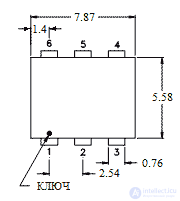
Figure 4. Appearance and dimensions of ADE mixers

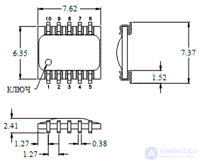
Figure 5. The appearance and size of the MBA mixers
Since the input and output impedances of the selected mixers are 50 Ohms, the circuit for switching on these radio receiver nodes is quite simple. It is shown in Figure 6.
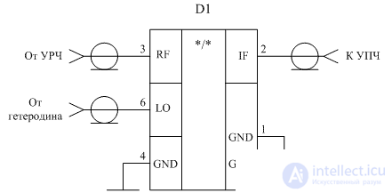
Figure 6. The scheme of the inclusion of the frequency mixer on the IC ADE-1L
When building modern production or cellular radio communications systems, it should be borne in mind that quite high frequencies are used in these communication systems. Therefore, when implementing high-frequency units of radio equipment, including frequency mixers, special attention should be paid to their design features. For example, all communication lines should be made in the form of microstrip lines, and separate nodes of receivers and transmitters should be shielded from electromagnetic radiation. Figure 7 shows the microstrip line design in which the signal conductor passes over the grounding surface of the printed circuit board.
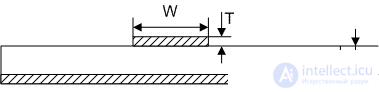
Figure 7. The design of the microstrip line with a given characteristic impedance
In this figure, W is the width of the signal conductor; T is the thickness of the deposition of copper; H is the dielectric thickness of a printed circuit board with electrical permeability  . It should be noted that for a specific PCB all parameters are fixed except for the width of the signal conductor. The impedance of the microstrip line can be found by the empirical formula:
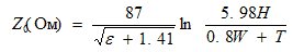 (2)
(2)
In this formula, the value of H is divided by W and T, with the result that a dimensionless coefficient is obtained. Therefore, these values can be substituted both in millimeters and in inches. For example, when using fiberglass FR-4 with a thickness of 0.5 mm and equal to 4.0, for the implementation of the wave resistance of 50 Ohm, the transmission line must be performed with a strip with a width of 0.5 mm. The thickness of the copper coating should be equal to 0.04 mm. To implement a wave resistance of 75 Ohms under the same conditions, the width of the conductor must be equal to 0.2 mm. More accurate calculations can be performed using the Wave Resistance Calculator, available at http://mcalc.sourceforge.net/#calc.
An example of the design of the mixer on the IC ADE-1L is shown in Figure 8.
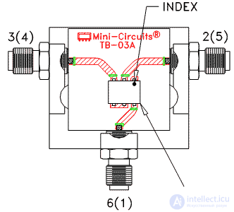
Figure 8. An example of the design of the frequency mixer on the IC ADE-1L
The figure clearly shows the strict adherence to the width of the conductors that supply the input signals. It is seen how structurally removed abrupt changes in direction in order to avoid reflection from the heterogeneity of the strip line.

Comments