Frequency response of the converter operating in linear mode.
To determine the frequency response of a transducer operating in linear mode, we will assume that a weak signal is fed to the transducer input, the frequency of which can be varied over a wide range, while maintaining the same local oscillator frequency.
At the last lesson, a direct conversion equation was obtained, which was used to determine the useful component of the output current of the converter. Complex current amplitude  wherein
 . (O)
. (O)
With  the frequency of the input signal takes values
 where
where  .
.
The minimum frequency of the signal at which a voltage drop is generated on the load is equal to  . Putting in expression (o)
  determine the amplitude of the current in the load frequency
 .(one)
In turn, the load voltage  due to current flowing through the load
  and determined by voltage phase
  ratio:
 . (2)
. (2)
Solving together equations (1) and (2) with respect to  will get
 ;
;
 ;
;
 ;
;
 .
.
Then the resonant gain of the mixer
 ,
,
Where  - meaning
  on frequency
  .
.
From the obtained expression it follows that the converter in this case works as an amplifier, only instead of the steepness in the amplifier mode  take the constant component of the slope in the conversion mode
A further increase in the frequency of the signal leads to the appearance of an input voltage at frequencies of the signal equal to
 ;
;  ;
;  ;
;
The gain of the transducer when using the kth harmonic of the conductivity  , can be determined by the formula obtained by us when considering the previous question
 .
.
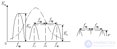
Thus, in the linear mode of operation of the frequency converter, its frequency response has the form shown in the figure, where the index at the mixer gain is determined by the corresponding number of the harmonic of the slope  .
.
Solid lines - frequency response of the converter.
Dotted - the frequency response of the preselector.

Figure 11.5.
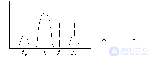
The resulting frequency response paths preselector and frequency converter.

Figure 11.6.
With the upper setting of the local oscillator and a simple transformation, i.e. with k = 1, the frequency of the main reception channel will be only the frequency  .
.
Frequency  symmetrically located in relation to the frequency
  , is called the frequency of the symmetric or mirror channel. The mirror channel is separated from the main one by a double value of the intermediate frequency. At the upper setting of the local oscillator
  .
.
Frequencies  ,
,  ,
,  ,
,  are the frequencies of the side channels of reception, since the signals of any radio station whose frequency coincides with one of these frequencies, create an intermediate frequency
  and are perceived as interference when receiving a signal with a frequency
  .
.
Ways to combat the harmful effects of side channels.
a) Selectivity to IF.
b) Selection of the operating mode of the inverter.
c) Selection of intermediate frequency.
but) Selectivity to IF . It is carried out using selective circuits in the receiver's selector. At the same time, side channels remain, however, up to the converter of the receiver, filtering of noise that can get into these channels is performed. Figure 1 shows the frequency response of the input circuit and receiver preselector (dotted line) and frequency response of the frequency converter (solid curves). Figure 2 shows the resulting frequency response of the radio frequency paths and the converter. According to Fig. 2, the gains in side channels are significantly reduced compared to the gain in the main channel.
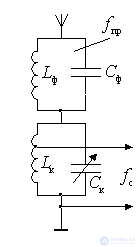
The selectivity for the channel with frequency  which does not change when rebuilding the receiver. If the channel selectivity at the intermediate frequency provided by the input circuit and the RF amplifier is insufficient, then the input of the PRCU includes a “filter plug” tuned to the frequency
  .
.

Figure 11.7.
Circuit  tuned to frequency
  , therefore its resistance at frequencies close to the frequency
  is great. Circuit
  tuned to frequency
  very different from
  . Therefore, for coles *** with frequency
  This circuit is very upset and its resistance is small. Therefore, the voltage with frequency
  will fall on the upper contour, and on the lower contour will be significantly weakened.
b) Selection of the mode of operation of the frequency converter . The basic rule for selecting the operating mode of the inverter is as follows: the offset to the converter element and the amplitude of the local oscillator must be chosen so that the gain of the inverter in the main channel is the greatest, and in the side channel - the smallest.
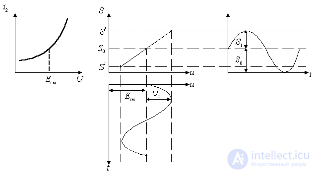
Because when converting on the first harmonic of the slope  converter slope
  , then the converter mode must be selected so that the first harmonic of the slope
  was as much as possible, and the rest as small as possible.

Figure 11.8.
The gain of the IF in the main and mirror channels is the same.
If the IVC of the converter element on the working section is quadratic. the offset on it is selected in the middle of the straight-line characteristic of the steepness, and the amplitude of the local oscillator is based on the condition of using the entire linear section, then only two side channels remain in the frequency converter: the mirror and at the intermediate frequency.
If the amplitude of the heterodyne is increased, then the first harmonic of the slope  will increase slightly, however, the level of its harmonics greatly increases.
In addition, to reduce the level of side channels using special inverter circuits, for example, balanced.
at) Selection of intermediate frequency . This choice is an important factor in the fight against side channels. When choosing a frequency  first of all are guided by the following considerations. M must be outside the range of received frequencies; it should not coincide with the frequencies of high-power stations. Frequency
  should have a standard value, because at such frequencies powerful radio stations do not work. To ensure higher selectivity in the image channel frequency
  should be as high as possible, and on the adjacent channel as low as possible.
In professional PRRU to create a high selectivity both in the mirror and the adjacent channels, apply multiple frequency conversion. With less  it is easier to obtain a higher sustained gain. However with increasing
  the frequency of the signal is more different from the frequency of the local oscillator, the oscillations of the local oscillator penetrate less into the antenna and, when they are radiated, create less interference with nearby receivers. With increasing
  the mass and dimensions of the selective circuits decrease, but the conjugate rearrangement of the selective circuits of the input circuit, RF amplifier and heterodyne becomes more complicated. From choice
  depends largely on the complexity of the construction of the local oscillator.
Frequency response of the converter operating in nonlinear mode.
If the frequency converter operates in a non-linear mode with respect to the signal voltage, then the number of side channels may increase significantly, i.e. In addition to the existing side channels, additional ones appear.
Nonlinear mode occurs when a signal with a sufficiently large amplitude acts on the converter input, at which, due to the non-linearity of the IVC of the mixer, higher harmonic components of the signal frequency and slope can create combination frequencies
 , (*)
, (*)
Where  - the harmonic number of the signal;
 - number of the harmonic of the slope.
The signal (useful or interfering) reaches the output of the converter only when the combination frequency  coincides with the intermediate frequency of the receiver. Putting in expression (*)
 ,
,
get an expression that determines the frequency of the side channels of reception  :
:
 ,
,
Theoretically, there are an infinite number of side channels. However, due to the fact that the amplitudes of the combinational components of the current in the output circuit of the mixer decrease with increasing k and n , only those side channels that correspond to the values of
 and
and  .
.
// Determine the frequency of the side channels from the condition that k and n vary from 1 to 3.//
Fighting interference by side channels.
To combat interference by side receiving channels caused by the non-linear mode of operation of the converter, the same methods are used as in the linear mode.
In addition to the measures applied in the linear mode, it is necessary to prevent excessive amplification in the preselector so that the frequency converter does not overload.


Comments
To leave a comment
Devices for the reception and processing of radio signals, Transmission, reception and processing of signals
Terms: Devices for the reception and processing of radio signals, Transmission, reception and processing of signals