Lecture
Purpose
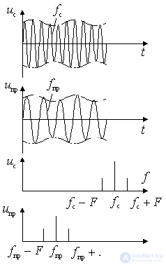
Frequency converters are used to transfer the frequency spectrum from one region to another without changing the nature of the modulation. They are part of a superheterodyne receiver.
The transformation results in a new value of the carrier frequency.  called intermediate. Frequency
  can be either higher or lower
  . If a
  - frequency conversion up;
 - frequency conversion down.

Figure 11.1.
Block diagram and principle of operation.
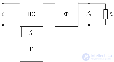
The frequency converter contains a nonlinear element and an auxiliary oscillation source, called the local oscillator. As a nonlinear element, various electronic devices, nonlinear active or reactive resistances are used. A nonlinear element that transforms a signal's *** of a signal using a local oscillator is called a mixer. The filter also includes a filter f with a load  required to isolate the intermediate frequency voltage.

Figure 11.2.
In general, frequency conversion can be considered as the result of multiplying two high-frequency voltages:
signal voltage

and local oscillator voltage
 .
.
As a result of such multiplication, the voltage of the converted frequency is obtained at the output of the converter
 .
.
Where  - constant coefficient depending on the parameters of the converter.
The amplitude, frequency, or phase of the converted voltage has the same law as the signal voltage. This means that when converting modulated signals, the type and modulation parameters are not violated.
Multiply the voltage in two ways: using nonlinear elements or using linear circuits with variable parameters (parametric circuits). In the general case, as a result of nonlinear or parametric conversion of two voltages at the output of the mixing element, a multitude of combination stress components with frequencies
 ,
,
where k and n are positive integers.
At the selective load, the voltage is allocated to one of the combination frequencies, which is taken as the intermediate frequency of the receiver.
The main characteristics of frequency converters.
one) Gain voltage.
 ,
,
Where  - intermediate frequency voltage at the output of the converter;
 - signal voltage at the input of the inverter.
2) Power gain
 ,
,
3) The working frequency range of the converter.
determined by the frequency range of the local oscillator with the given value of the intermediate frequency.
four) Selectivity converter.
depends on the type of frequency response of its load. However, when tuning the local oscillator corresponding to the reception of a useful signal, there are a number of frequencies that, as a result of the conversion, also form an intermediate frequency (for example,  or
or  ). Consequently, there are side reception channels in the frequency converter that degrade its selective properties.
five) Input and output conductance.
6) Converter noise ratio.
7) The level of linear and nonlinear distortion.
eight) Stability of work.
9) The reliability of the inverter and others.
Classification IF.
According to the method of obtaining  :
:
- IF with the upper setting of the local oscillator
 i.e.
i.e.  .
.
In this case, after the transformation, the position of the sidebands of the signal changes, i.e. lower becomes upper and vice versa ( inverting frequency conversion ).
- IF with lower local oscillator setting.
 i.e.
i.e.  .
.
In this case, the position of the sidebands of the signal relative to the carrier frequency after conversion does not change ( non-inverting frequency conversion ).
By type of nonlinear element:
- diode frequency converter;
- transistor IF;
- integrated frequency converter.
By the number of nonlinear elements in the inverter:
- simple (one ne);
- balanced (two ne);
- ring (four ne).
Comments
To leave a comment
Devices for the reception and processing of radio signals, Transmission, reception and processing of signals
Terms: Devices for the reception and processing of radio signals, Transmission, reception and processing of signals