Lecture
Given:
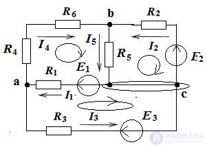
R1 = R5 = 10 Ohm, R4 = R6 = 5 Ohm, R3 = 25 Ohm, R2 = 20 Ohm, E1 = 100 V, E2 = 80 V, E3 = 50 V 
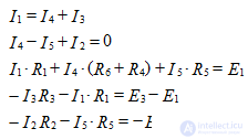
We determine the number of nodes, branches and independent contours: q = 3, p = 5, contours 3. We make equations according to Kirchhoff's laws: the equations according to the 1st Kirchhoff's law are 2, and the equations according to the 2nd Kirchhoff's law are 3. for the nodes of a and b. For contours, select the clockwise roundabouts: 
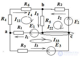
Since there are three circuits, there will be three loop currents I11, I22, I33. We select the directions of these currents clockwise in Fig. 3. Let us write the real currents through the contour:
I1 = I11 - I33, I2 = - I22, I3 = - I33, I4 = I11, I5 = I11 - I22
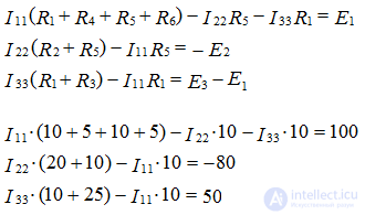
We write the equation according to the second Kirchhoff law for contour equations in accordance with the rules.
The rule is: if the emf and current have the same direction as the circuit bypass direction, then they are taken from “+”, if not, then from “-”. 

Solve the system of equations by the mathematical method of Gauss or Cramer. 
Solving the system, we obtain the values of the contour currents:
I11 = 2.48 A, I22 = - 1.84 A, I33 = - 0.72 A
We define these currents:
I1 = 3.2 A,
I2 = 1.84 A,
I3 = 0.72 A,
I4 = 2.48 A,
I5 = 4.32 A
Check the correctness of the calculation of currents, substituting them into the equation according to the laws of Kirchhoff.
Create equations for calculating the balance of power: 
From the calculation it is clear that the balance of power has come together. The error is less than 1%
Comments
To leave a comment
Electrical Engineering, Circuit design
Terms: Electrical Engineering, Circuit design