Lecture


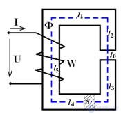
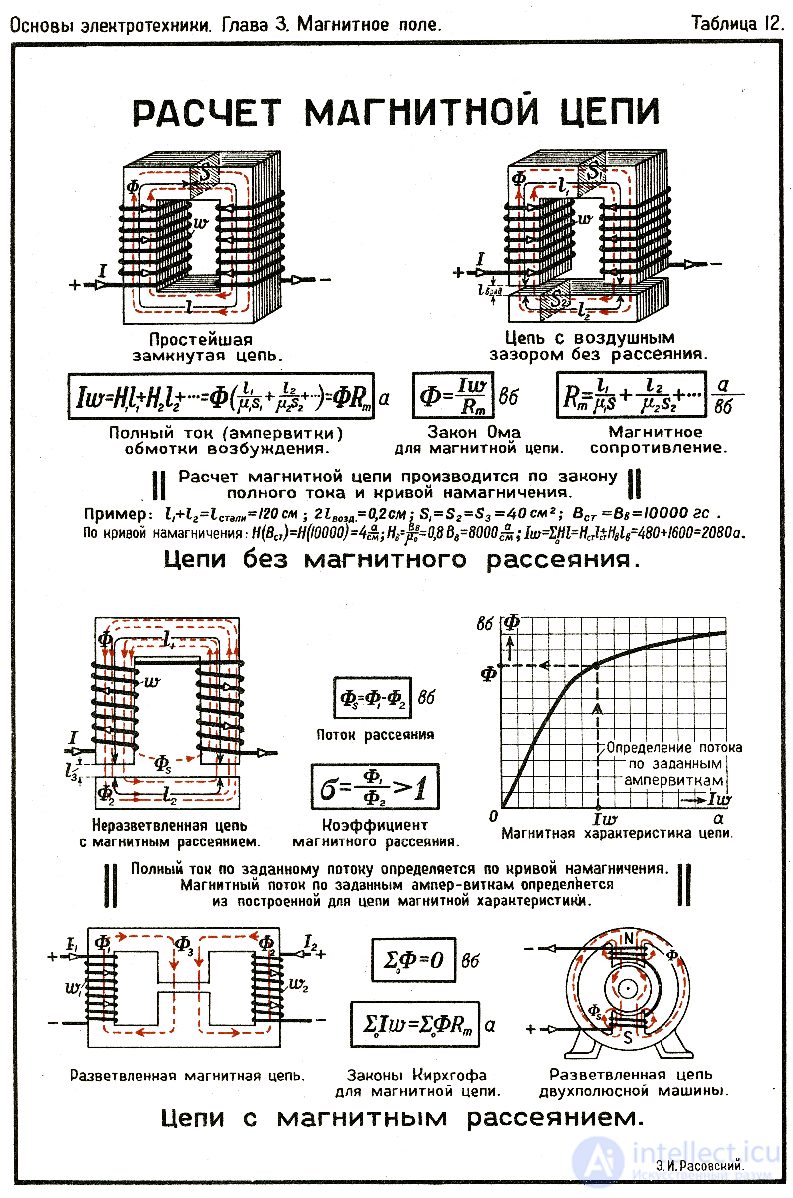
Magnetic circuits are calculated similarly to electrical ones, but instead of voltage, current and resistance, magnetic voltage (F), magnetic flux (Φ) and magnetic resistance (R) are used.
Basic equation:
F=ΦR
where
F=NI is the magnetomotive force (MMF) created by current I in a winding with N turns.
Φ is the magnetic flux in Webers.
R=μSl is the magnetic resistance, depending on the length of the magnetic circuit lll, the cross-sectional area S and the magnetic permeability μ.
For complex circuits, analogs of Kirchhoff's laws are used:
First law: the sum of magnetic fluxes in a node is zero.
Second law: the sum of magnetic voltages in a circuit is equal to the MMF.

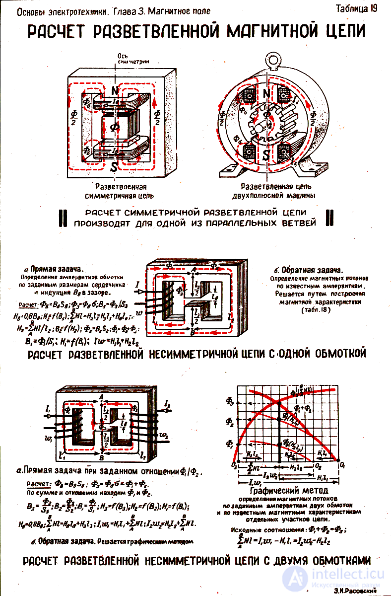
A branched magnetic circuit is an analog of a branched electric circuit, where magnetic fluxes are divided between different branches. The solution usually includes:
Determining the circuit topology (nodes, branches, loops).
Writing Kirchhoff's equations for magnetic circuits:
The sum of magnetic voltages (F) in a loop is zero.
The sum of fluxes (Φ) in a node is zero.
Calculating magnetic resistances (R=l/(μS)).
Solving a system of equations (e.g., using the nodal potential method or the loop current method).

Comments
To leave a comment
Electrical Engineering, Circuit design
Terms: Electrical Engineering, Circuit design