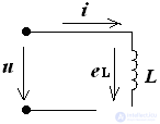
The ideal inductor has an active resistance of RL = 0.
i (t) = Imsin (ωt + ψi)
eL = - L = - LωImcos (ωt + ψi)
eL = Emsin (ωt + i + 90 °)
u = - eL;
u (t) = Um sin (ωt + ψu)
initial phase ψu = ψi + 90 °
phase angle φ = ψu - ψi = 90 °
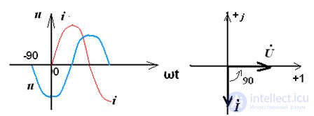
It can be seen from the vector diagram that the voltage on the inductance voltage is ahead of the current by 90 °, since φ = 90 °, then
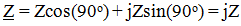
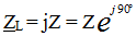
,
and the modulus of complex resistance is Z = XL = ωL, therefore, the resistance is purely reactive and is:
Ohm's Law: U = I • (XL)
Power on L - element:

the phase angle φ = 90 °, then
P = UIcosφ = 0, Q = UIsinφ = UI, therefore on the L - element there is an exchange of energy between the source of electrical energy and the magnetic field of the coil, which determines the reactive power Q. L - element does not perform work, therefore the active power is 0.

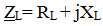
A real coil has an active resistance determined by the resistance of the wires, therefore the total impedance is equal to:

Comments
To leave a comment
Electrical Engineering, Circuit design
Terms: Electrical Engineering, Circuit design