Definition of nonlinear element
In practice, in industrial electronics, electrical circuits consist mainly of nonlinear elements, i.e. of elements whose current-voltage characteristics are not a straight line (the parameter values change drastically with current)
All non-linear CVCs have all semiconductor devices:
Semiconductor diodes, zener diodes, thermistors, transistors, thyristors, etc.
The analysis and calculation of nonlinear circuits is carried out using the method of intersection of characteristics, the equivalent method, of an active two-port network.
Characteristics and parameters of the nonlinear element
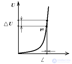
The concepts of static and dynamic (differential) resistance
Pic 1
Rct = Urt / Ipt - the ratio of the voltage on the element to the current at a given point of its characteristics
Rdin = dU / dI = ∆U / ∆I - the ratio of the change in voltage to the change in current in a given working area of a nonlinear element Rst> Rdin
Nonlinear Circuit Analysis
It is carried out in two ways analytically or graphically - by intersecting the characteristics - this is the solution of the non-linear equation determining the electrical state in a graphical way.
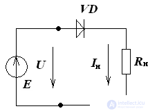
Consider a section of a circuit with series-connected linear and non-linear elements.
(pic 2).
Pic 2
Pic 3
We make the equation of the electric state for the circuit of Fig.2:
U = E - Rn • I
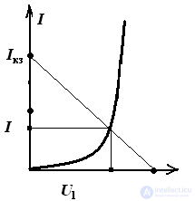
According to this equation, the “inverted” I – V characteristic of the resistor RH (or the load line) is constructed.
Rule: if a nonlinear element is connected in series with a resistor, then an “inverted” I – V characteristic is constructed; if in parallel, then a normal I – V characteristic of the resistor is constructed.
As you know, any straight line is built on two points, which correspond to two modes of a two-terminal network with parameters E and Rn.
Idling: I = 0; U = E
Short circuit: U = 0; Ikz = E / Rn
The intersection of the current-voltage characteristics of the nonlinear element and the resistor give a graphical solution to the problem, as shown in Fig. 3
In the analysis of nonlinear circuits, an equivalent generator method is used, in the case of a complex circuit: A multi-element active linear two-pole network, to the output terminals of which a non-linear element is connected, can be replaced by an equivalent two-pole network. The voltage and current on the nonlinear element are found by intersecting characteristics, knowing these parameters you can determine the currents and voltages of the other branches of the circuit.
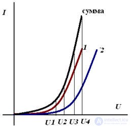
In the case of series-connected nonlinear elements, firstly, the IV characteristics of the elements are graphically folded, and then the calculation is carried out as shown earlier.
Addition of the current-voltage characteristic, with the series connection of nonlinear elements
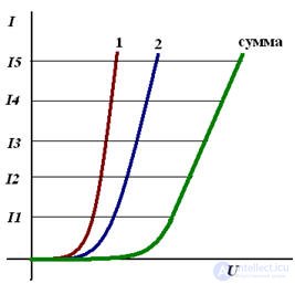 Addition of VAC, with parallel connection of nonlinear elements


Comments
To leave a comment
Electrical Engineering, Circuit design
Terms: Electrical Engineering, Circuit design