Lecture
The magnetic field can exhibit two actions: induction and electrodynamic.
Electrodynamic property is based on the phenomenon of electromagnetic induction, i.e. induction of EMF in a conductor with an alternating magnetic field. This property is used in devices included in the AC circuit (chokes, transformers, electrical measuring instruments, in direct current devices, etc.)
Electrodynamic action is associated with the force of a magnetic field on a charge, wire, or magnetized body. This action is fundamental for devices in which there are moving parts, and the purpose of these devices is the creation of mechanical forces (torque), moments: electromagnetic relays, electric motors, etc.
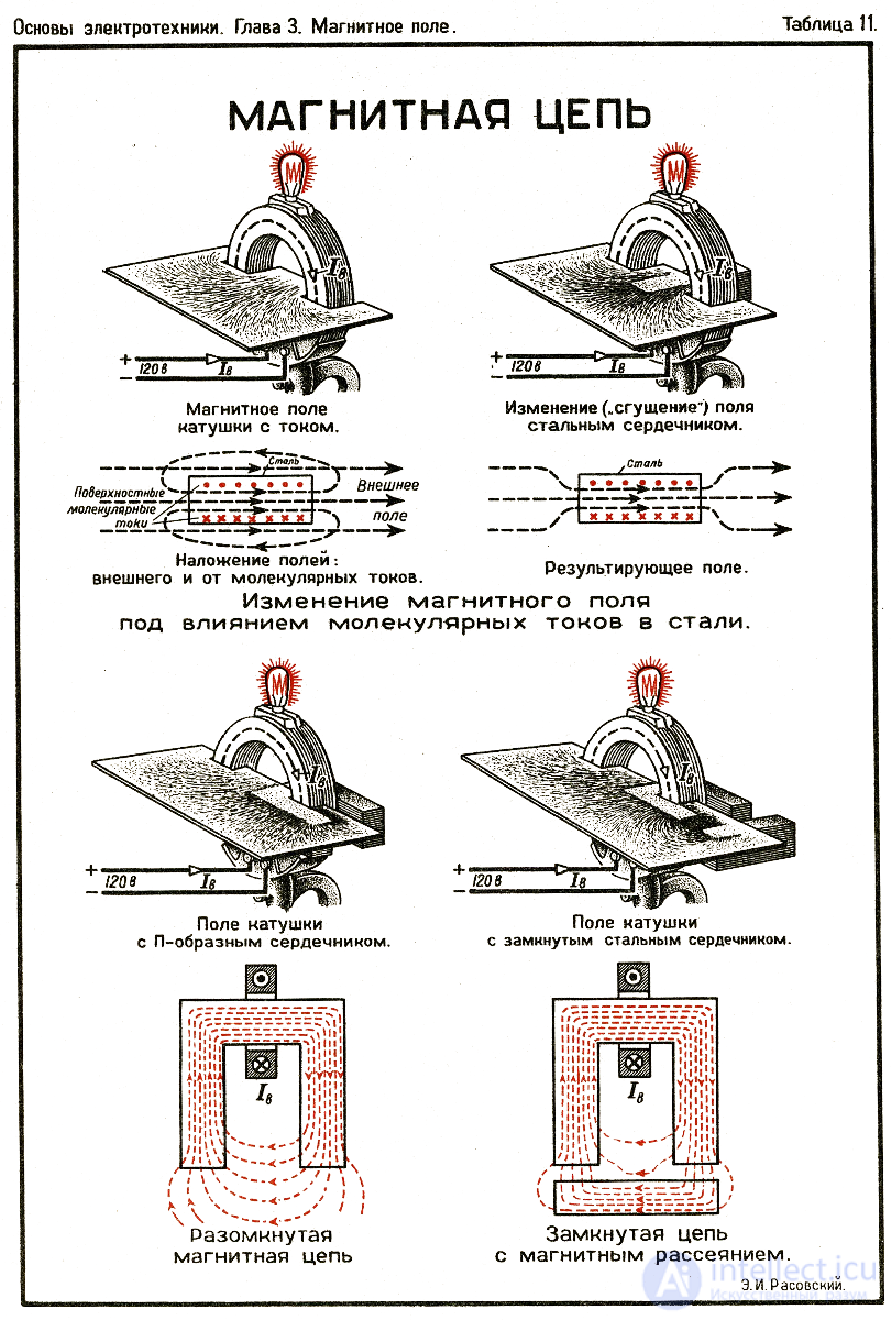
Magnetic flux amplification is carried out with the help of ferromagnetic - rational use of the magnetic field.
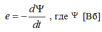
EMF is induced in a moving magnetic field:
 - coil flux coupling with magnetic field
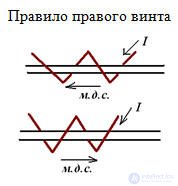
The direction of the EMF will be recognized using the right-hand method when the lines of force enter the palm, and the retracted thumb indicates the direction of movement.
Change  may occur as a result of changes in the magnetic field or movement of the coil. The emf is set so that its induced current creates a magnetic field that reduces the change in flux coupling.
Basic concepts:
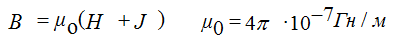
Magnetic induction B (T) - determines the force of the magnetic field on the current.
The magnetization J is the magnetic moment of a unit volume of a substance (current density).
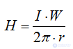
Magnetic field strength H (A / m).
Magnetomotive force (ppm) F (A)
(ppm) F = W • I = H · l, ppm causes magnetic flux in a magnetic circuit.
μo = constant characterizing magnetic properties in vacuum.
Magnetic flux - F (WB)
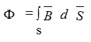
for an air gap reel:
F = B • S0 = μ • H • S0
for ferromagnetic materials, therefore, in order to reduce ppm and reduce the current coil supply ferromagnetic material (core)

Straight chain (toroids, choke).
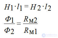
Branched chains (symmetrical I1 • W1 = I2 • W2, asymmetrical I1 • W1 # I2 • W2).
(transformers, etc.)
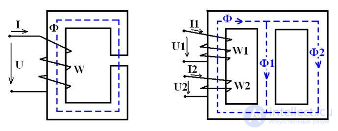
Figure 6
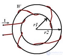
In parallel branches of a branched magnetic circuit with H1 and H2 and middle lines l1 and l2
Kirchhoff's laws for magnetic circuits
1st law - the algebraic sum of magnetic fluxes in any node of the magnetic circuit is 0.

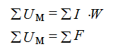
The 2nd law - the algebraic sum of the magnetic voltage drops Um = H ∙ l along any closed contour is equal to the algebraic sum of the ppm.
EMU with constant magnetic fluxes
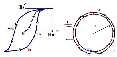
Figure 7
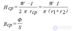
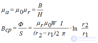
Toroid with thick walls
Pic 8
Absolute Magnetic Permeability and Induction

Comments