
Lecture
Texture ( English: Texture mapping ) — is a method of imparting properties to the surface of a 3D part — a polygon: color, texture, gloss, matte finish, and other physical properties (most often to imitate some natural material, for example paper, wood, stone, metal, etc.).
The concept of a "texture" is an important element of 3D modeling, since it allows the reproduction of small surface objects whose creation using polygons would be excessively resource-intensive. For example, scars on skin, folds in clothing, small stones, objects on the surface of walls and ground, and much more. Thus, a texture is used to fill the surfaces of objects and as a layer to impart a particular effect or to alter the geometry of the entire image or part of it.
Textures can be seamed or seamless (patterns). The main difference of the latter is that when the same fragments are combined, the surface remains continuous.
The surface quality of a texture is determined by texels – the number of pixels per minimum texture unit. Since a texture is itself an image, its resolution and format play a large role, which subsequently affects the overall impression of graphics quality in a 3D application.
Material parameters are created by using maps (images) placed in the corresponding channels, or with the help of procedural maps, as well as a mixed method.
Texture mapping — is a method of applying a texture to computer graphics. «Texture» in this context can be high-frequency detail, surface texture, or color.
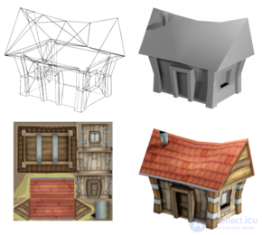
Mapping a two-dimensional texture onto a three-dimensional model
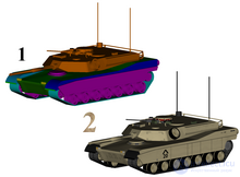
1: 3D model without textures
2: The same model with textures
A texture map is applied to create a particular parameter of the visual display of a surface of a given shape. This process resembles applying patterned paper to a plain white box. Each vertex in the 3D model is assigned texture coordinates (which in the 2D case is known as a UV coordinate). The image sampling locations are subsequently interpolated across the model's surface to produce the visual result.
Most often this is a raster (less often vector) image file with the extension JPEG, PNG, or PAT.
The original technique was first proposed by Edwin Catmull in 1974 as part of his doctoral dissertation.
Texture mapping originally referred to diffuse mapping, a method that simply mapped pixels from a texture onto a 3D surface («wrapping» the image around the object). In recent decades, the emergence of multi-pass rendering, multitexturing, MIP maps, and more complex mappings such as height mapping, bump mapping, normal mapping, displacement mapping, reflection mapping, specular mapping, occlusion mapping, and many other variations of the technique (managed by the material system) have made it possible to simulate near-photorealism in real time while significantly reducing the number of polygons and lighting calculations needed to build a realistic and functional 3D scene.
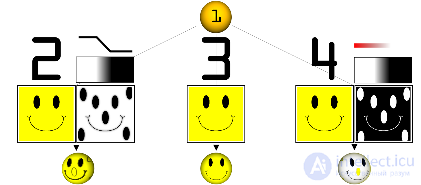
Examples of multitexturing:
1: Untextured sphere, 2: Texture and bump maps, 3: Texture map only, 4: Opacity and texture maps
Example of multitexture applied to an object: 1. Sphere onto which are applied: 2. Diffuse and bump maps; 3. Diffuse map only; 4: Opacity and Diffuse maps.
A texture map — is an image applied (mapped) to the surface of a shape or polygon. It can be a raster image or a procedural texture. They can be stored in common image file formats, referenced by 3D model formats or material definitions, and assembled into asset packages.
They can have from one to three dimensions, although two dimensions are most commonly used for visible surfaces. For use with modern hardware, texture map data can be stored in swizzled or tiled order to improve cache coherency. Rendering APIs generally manage texture map resources (which may reside in device memory) as buffers or surfaces, and may allow «render to texture» for additional effects such as post-processing or environment mapping.
They typically contain RGB color data (stored as direct color, compressed formats, or indexed color), and sometimes an additional channel for alpha blending (RGBA), especially for billboards and decal overlay textures. The alpha channel (which can conveniently be stored in hardware-parsed formats) can be used for other purposes, such as specularity.
Several texture maps (or channels) can be combined to control specularity, normals, displacement, or subsurface scattering, for example for rendering skin.
Multiple texture images can be combined into texture atlases or texture arrays to reduce state changes for modern hardware. (These can be considered a modern evolution of tile map graphics). Modern hardware often supports multi-face cube map textures for environment mapping.
Texture maps can be obtained by scanning / digital photography, developed in image editing software such as GIMP or Photoshop, or painted directly onto 3D surfaces in a 3D painting tool such as Mudbox or ZBrush.
This process is similar to applying patterned paper to a plain white box. Each vertex in the polygon is assigned a texture coordinate (which in the 2D case is also known as UV coordinates). This can be done through explicit assignment of vertex attributes, manually edited in a 3D modeling package using UV unwrapping tools. It is also possible to associate a procedural transformation from 3D space to texture space with the material. This can be achieved through planar projection or, alternatively, cylindrical or spherical mapping. More sophisticated mappings can take into account the distance along the surface to minimize distortion. These coordinates are interpolated across the polygon faces to sample the texture map during rendering. Textures can be repeated or mirrored to extend the final rectangular bitmap over a larger area, or they can have a unique «injective» one-to-one mapping from each part of the surface (which is important for render mapping and light mapping, also known as baking).
Texture mapping maps the surface of a model (or screen space during rasterization) into texture space; in this space, the texture map is visible undistorted. UV unwrapping tools typically provide a view in texture space for manual editing of texture coordinates. Some rendering techniques, such as subsurface scattering, can be performed approximately using operations in texture space.
Multitexturing — is the use of more than one texture at a time on a polygon. For example, a light map texture can be used to illuminate a surface as an alternative to recalculating that lighting each time the surface is rendered. Microtextures or detail textures are used to add higher-frequency detail, and dirt maps can add weathering and variation; this can significantly reduce the apparent periodicity of repeating textures. Modern graphics may use more than 10 layers, which are combined using shaders, for greater precision. Another multitexturing method — is bump mapping, which allows a texture to directly control the surface direction for the purposes of its lighting calculations; it can give a very good appearance of a complex surface (such as tree bark or rough concrete), which acquires lighting detail in addition to the usual detailed coloring. Bump mapping became popular in recent video games as graphics hardware became powerful enough to handle it in real time.
The way in which samples (for example, when viewed as pixels on a screen) are computed from texels (texture pixels) is governed by texture filtering. The cheapest method — is to use nearest-neighbor interpolation, but bilinear interpolation or trilinear interpolation between MIP maps — are two commonly used alternatives that reduce aliasing or jaggedness. In cases where the texture coordinate falls outside the texture, it is either clamped or wrapped. Anisotropic filtering better eliminates directional artifacts when viewing textures from oblique viewing angles.
Texture streaming — is a way of using data streams for textures, where each texture is available in two or more different resolutions, to determine which texture should be loaded into memory and used based on the distance from the viewer and the amount of memory available for textures. Texture streaming allows the rendering engine to use low-resolution textures for objects far from the viewer's camera and to switch to more detailed textures, read from a data source, as the viewpoint approaches the objects.
As an optimization, one can render details from a complex high-resolution model or an expensive process (such as global illumination) into a surface texture (possibly on a low-resolution model). Baking is also known as render mapping. This technique is most often used for light maps, but can also be used to generate normal maps and displacement maps. Some computer games (such as Messiah) have used this technique. The original Quake software engine used on-the-fly baking to combine light maps and color maps («surface caching»).
Baking can be used as a form of level-of-detail generation, where a complex scene with many different elements and materials can be approximated by a single element with a single texture, which is then algorithmically reduced to lower rendering cost and reduce the number of draw calls. It is also used to take highly detailed models from 3D sculpting software and point cloud scanning and approximate them with meshes more suitable for real-time rendering.
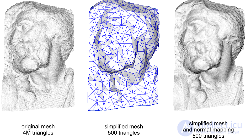
Example of using a normal map to reduce the polygon count of a model without loss of visual display quality.
Normal maps are usually of two types: object-space — used for non-deformable objects such as walls, doors, weapons, etc.; tangent-space – used for the ability to deform objects, such as characters. To create normal maps, high-poly and low-poly models are traditionally used, and by comparing them the appropriate value of normal deviation is established.
Different methods have evolved in software and hardware implementations. Each offers different trade-offs in accuracy, versatility, and performance.
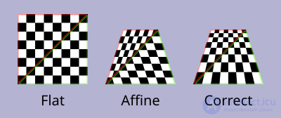
Because affine texturing does not account for depth information of the polygon's vertices, when the polygon is not perpendicular to the viewer, it produces a noticeable defect, especially when rasterizing as triangles.
Affine texture mapping linearly interpolates texture coordinates across the surface, and is therefore the fastest form of texture mapping. Some software and hardware (such as the original PlayStation) project vertices in three-dimensional space onto the screen during rendering and linearly interpolate texture coordinates in screen space between them. This can be done by incrementing fixed-point UV coordinates or using an incremental error algorithm similar to Bresenham's line algorithm.
Unlike with perpendicular polygons, this leads to noticeable distortion under perspective transformations (see figure: the flag texture appears curved), especially for primitives near the camera. Such distortion can be reduced by subdividing the polygon into smaller ones.
For rectangular objects, using quad primitives may look less incorrect than the same rectangle split into triangles, but because interpolating 4 points complicates rasterization, most early implementations preferred triangles only. Some hardware, such as the direct texture mapping used by the Nvidia NV1, could offer efficient quad primitives. With perspective correction (see below), triangles become equivalent and this advantage disappears.
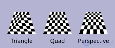
For rectangular objects, especially those perpendicular to the view, linear interpolation across a quad can give a superior affine result compared to the same rectangle split into two affine triangles.
For rectangular objects that are at a right angle to the viewer, such as floors and walls, perspective only needs to be corrected in one direction across the screen, not both. The correct perspective mapping can be calculated for the left and right edges of the floor, and then affine linear interpolation across this horizontal span will look correct, since every pixel along that line is at the same distance from the viewer.
Texturing with correct perspective takes into account the position of vertices in three-dimensional space, rather than simply interpolating coordinates in two-dimensional screen space. This achieves the correct visual effect but requires greater computational cost.
To perform perspective correction of texture coordinates 
 ,
,  being the depth component from the viewer's perspective, we can take advantage of the fact that the values
  ,
,  , and
, and  are linear in screen space across the entire textured surface. Unlike the original , and , before division, are not linear across the surface in screen space. Therefore we can linearly interpolate these reciprocal values across the surface, computing corrected values at each pixel to obtain a perspective-correct texture mapping.
To do this we first compute the reciprocal values at each vertex of our geometry (3 points for a triangle). For vertex  we have
  . We then linearly interpolate these reciprocal values between the vertices (for example, using barycentric coordinates), which yields interpolated values across the whole surface. At a given point, this gives an interpolated value,
  , from
 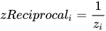 . Note that this cannot yet be used as texture coordinates, since our division by changed its coordinate system.
To correct back into  space, we first compute the corrected again by taking the reciprocal of
 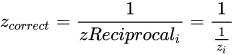 . We then use this to correct our :
  and
and  .
.
This correction makes it so that in parts of the polygon that are closer to the observer, the pixel-to-pixel difference between texture coordinates is smaller (the texture is stretched wider), while in parts that are farther away, this difference is larger (the texture is compressed).
Affine texture mapping directly interpolates the texture coordinates  between two endpoints
  and
and  :
:
 where
where 
Perspective-correct mapping is interpolated after dividing by depth  , then uses its interpolated reciprocal value to recover the correct coordinate:
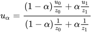
3D graphics hardware generally supports texturing with correct perspective.
Various methods have been developed for rendering textured geometry into images with different trade-offs between quality and accuracy, which can be applied to both software and hardware.
Classic software texture mappers usually performed only simple mapping with at most one lighting effect (usually applied via a lookup table), and perspective correctness cost approximately 16 times more.
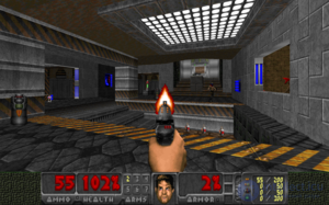
The Doom engine did not allow sloped floors or sloped walls. This requires perspective correction only once per horizontal or vertical span, rather than per pixel.
The Doom engine restricted the world to vertical walls and horizontal floors/ceilings, with a camera that could only rotate around the vertical axis. This meant that walls would have a constant depth coordinate along a vertical line, and floors/ceilings would have a constant depth along a horizontal line. After performing a single perspective-correction calculation for depth, the rest of the line could use fast affine mapping. Some later renderers of that era simulated a small amount of camera tilt with shearing, which created the appearance of greater freedom while using the same rendering technique.
Some engines are capable of rendering height maps with texture overlay (such as Nova Logic's Voxel Space and the engine for Outcast) using incremental algorithms similar to Bresenham's algorithm, creating the appearance of a textured landscape without using traditional geometric primitives.
Each triangle can be further subdivided into groups of approximately 16 pixels to achieve two goals. First, keeping the arithmetic pipeline running at all times. Second, obtaining faster arithmetic results.
For perspective texture mapping without hardware support, a triangle is subdivided into smaller triangles for rendering, and affine mapping is applied to them. The reason this method works is that the distortion of affine mapping becomes much less noticeable on smaller polygons. The Sony PlayStation made extensive use of this, since it only supported affine mapping at the hardware level, but had a relatively high triangle throughput compared to its counterparts.
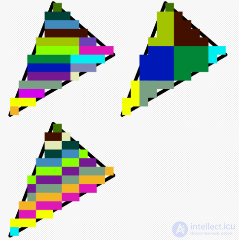
Screen-space subdivision methods.
Software renderers generally prefer screen-space subdivision, since it has lower overhead. In addition, they attempt to perform linear interpolation along a line of pixels to simplify setup (compared to 2D affine interpolation) and thus again reduce overhead (also, affine texturing does not fit well into the small number of registers on an x86 processor; a 68000 or any RISC processor is much better suited).
For Quake, a different approach was used, which would compute correct-perspective coordinates only once every 16 pixels of a scanline and perform linear interpolation between them, effectively working at the speed of linear interpolation, since the correct-perspective calculation was performed in parallel on a coprocessor. Polygons are rendered independently, so it is possible to switch between spans and columns, or diagonal directions, depending on the orientation of the polygon's normal, to achieve a more constant z, but the effort does not seem to have been worth it.
Another method involved approximating perspective with a faster calculation, such as a polynomial. Yet another method used the 1/z value of the last two drawn pixels to linearly extrapolate the next value. Division was then performed starting from these values, so that only a small remainder was divided, but the amount of bookkeeping makes this method too slow on most systems.
Finally, the Build engine extended the constant-distance trick used in Doom, finding a line of constant distance for arbitrary polygons and rendering along it.
Texture mapping hardware was originally developed for simulation (for example, as implemented in Evans and Sutherland ESIG and Singer-Link Digital Image Generators DIG), as well as for professional graphics workstations such as Silicon Graphics, machines for creating digital video effects such as Ampex ADO, and later appeared in arcade machines, consumer game consoles, and PC video cards in the mid-1990s. In flight simulation, texture mapping provided important motion and altitude cues needed for pilot training that were unavailable on untextured surfaces. Also, in flight simulation applications, texture mapping was implemented for real-time processing using pre-filtered texture patterns stored in memory for real-time access by the video processor.
Modern graphics processing units (GPUs) provide specialized fixed-function units called texture samplers or texture mapping units to perform texture mapping, usually with trilinear filtering or better multi-tap anisotropic filtering, and hardware for decoding specific formats such as DXTn. As of 2016, texture mapping hardware has become ubiquitous, as most SoCs contain a suitable GPU.
Some hardware combines texture mapping with hidden-surface determination in tile-based deferred rendering or scanline rendering; such systems fetch only visible texels at the cost of using more workspace for transformed vertices. Most systems have settled on the Z-buffering approach, which can still reduce the texture mapping workload with front-to-back sorting.
Among earlier graphics devices, there were two competing paradigms for outputting texture to the screen:
Inverse texture mapping — is the method that has become the standard in modern hardware.
Using this method, a pixel on the screen is mapped to a point on the texture. Each vertex of the rendering primitive is projected to a point on the screen, and each of these points is mapped to a texel coordinate u,v on the texture. The rasterizer will interpolate between these points to fill in each pixel covered by the primitive.
The main advantage is that each pixel covered by the primitive will be visited exactly once. After the primitive's vertices are transformed, the amount of remaining work depends directly on how many pixels it covers on the screen.
The main disadvantage compared to forward texture mapping is that the memory access pattern in texture space will not be linear if the texture is at an angle to the screen. This drawback is often mitigated by texture caching methods, such as swizzled texture memory layout.
Linear interpolation can be used directly for simple and efficient affine texturing, but it can also be adapted to provide perspective correctness.
Forward texture mapping maps each texel of the texture to a pixel on the screen. After transforming the rectangular primitive to a location on the screen, a forward texture mapping renderer iterates over each texel of the texture, applying each one to a frame buffer pixel.
This was used in some hardware, such as the 3DO, Sega Saturn, and NV1.
The main advantage is that texture access will occur in simple linear order, which allows very efficient caching of texture data. However, this advantage is also its drawback: as the primitive becomes smaller on the screen, it still has to iterate over every texel in the texture, resulting in redundant overdraw of many pixels.
This method is also well suited for rendering quad primitives rather than reducing them to triangles, which gave an advantage when correct perspective texturing was not available at the hardware level. This is because the affine distortion of a quad looks less incorrect than the same quad split into two triangles (see affine texture mapping above). The NV1 hardware also allowed the use of a quadratic interpolation mode to provide an even better approximation of perspective correctness.
Existing hardware implementations did not provide efficient mapping of UV coordinates, which became an important technique for 3D modeling and helped correctly clip the texture when a primitive extends beyond the edge of the screen. These shortcomings could have been addressed with further development, but since then GPU design has largely shifted to inverse mapping.
Beyond 3D rendering, the availability of texture mapping hardware inspired its use for accelerating other tasks:
Texture mapping hardware can be used to accelerate both the reconstruction of voxel datasets from tomographic scans and the visualization of the results.
Many user interfaces use texture mapping to accelerate animated transitions of screen elements, such as Exposé in Mac OS X.

Comments