
Lecture
Rendering — is the process of creating a photorealistic or non-photorealistic image from input data, such as 3D models . The word «rendering» (in one of its meanings) originally meant the task performed by an artist in depicting a real or imagined thing (the finished work of art is also called a « rendering »). Today «rendering» usually means creating an image or video from a precise description (often created by an artist) with the help of a computer program .
A software application or component that performs rendering is called a rendering engine , a rendering engine , a rendering system , a graphics engine , or simply a renderer .
A distinction is made between real-time rendering , in which images are generated and displayed immediately (ideally quickly enough to create the impression of motion or animation), and offline rendering (sometimes called pre-rendering ), in which images or frames of films or videos are generated for later viewing. Offline rendering can use a slower, higher-quality renderer. Interactive applications, such as games, must primarily use real-time rendering, although they may include pre-rendered content.
Rendering can produce images of scenes or objects defined using coordinates in three-dimensional space , viewed from a particular point of view . Such three-dimensional rendering uses knowledge and ideas from optics , the study of visual perception , mathematics , and software development , and has applications such as video games , simulators , visual effects for film and television, design visualization, and medical diagnostics . Realistic three-dimensional rendering requires finding approximate solutions to the rendering equation , which describes how light propagates in a medium.

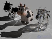
Image rendered using POV-Ray 3.6
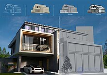
Architectural visualization done in several styles using Blender
Real-time rendering uses high-performance rasterization algorithms , which process a list of shapes and determine which pixels are covered by each shape. When more realism is required (for example, for architectural visualization or visual effects ), slower per-pixel algorithms are used instead, such as ray tracing . (Ray tracing can also be used selectively during rasterized rendering to enhance the realism of lighting and reflections.) A type of ray tracing called path tracing is currently the most common technique for photorealistic rendering. Path tracing is also popular for creating high-quality non-photorealistic images, such as frames for 3D cartoons. Both rasterization and ray tracing can be accelerated («hardware-accelerated») by specially designed microprocessors called graphics processing units .
Rasterization algorithms are also used to render images containing only two-dimensional shapes, such as polygons and text . Applications of this type of rendering include digital illustration , graphic design , two-dimensional animation , desktop publishing , and user interface rendering .
Historically, rendering was called image synthesis , but today this term more likely refers to image generation using artificial intelligence . The term «neural rendering» is sometimes used when a neural network is the primary means of generating the image, but some degree of control over the output image is still provided. Neural networks can also assist in rendering without replacing traditional algorithms, for example by removing noise from path-traced images.
Rendering, computer visualization (from the English word rendering — visualization, drawing, representation) — is the process of obtaining an image from a two-dimensional or three-dimensional model (a scene file). The word rendering is used to denote the process of visualization performed with the help of software, while render denotes the finished image, that is, as synonyms for the phrases: computer visualization - computer rendering, visualized object - render.
At present, many visualization algorithms have been developed. Existing software can use several algorithms simultaneously to obtain the final image. There is a clear trend toward implementing rendering algorithms at the hardware level.
The key to the theoretical justification of rendering models is the rendering equation. It is the most complete formal description of the part of rendering that is not related to the perception of the final image. All models are some approximate solution of this equation.

The physical basis of the equation is the law of conservation of energy. An informal interpretation is as follows: the amount of light radiation (𝐿𝑜) leaving a given point in a given direction is the sum of its own emission and reflected radiation. Reflected radiation is the sum, over all directions, of incoming radiation (𝐿𝑖) multiplied by the reflectance coefficient at the given angle. By combining, in a single equation, the incoming radiation with the emitted radiation at one point, this equation forms a description of the entire light flux in a given system. Various computer graphics algorithms solve this fundamental equation.
A rendered image can be understood in terms of a number of visible features. Research and development in the field of visualization is largely motivated by the search for ways to simulate them efficiently. Some of them are directly related to specific algorithms and methods, while others are produced together.
Before a 3D scene or 2D image can be rendered, it must be described in a way that the rendering software can understand. Historically, the input data for 2D and 3D rendering was usually text files , which are easier for people to edit and debug than binary files. For 3D graphics, text formats have largely been displaced by more efficient binary formats and APIs, which allow interactive applications to communicate directly with the rendering component without creating a file on disk (although a description of the scene is usually still created in memory before rendering).
Traditional rendering algorithms use geometric descriptions of 3D scenes or 2D images. Applications and algorithms that render data scanned from the real world, or scientific simulations , may require various types of input data.
The PostScript format (which is often credited with the growth of desktop publishing ) provides a standardized, compatible way of describing 2D graphics and page layout . The Scalable Vector Graphics (SVG) format is also text-based, and the PDF format uses the PostScript language internally. In contrast, although many 3D graphics file formats have been standardized (including text formats such as VRML and X3D ), various rendering applications typically use formats tailored to their needs, and this has led to a proliferation of proprietary and open formats, with binary files being more common.
A description of a vector graphic image may include:
A description of a geometric scene may include:
There are many file formats for storing individual 3D objects or « models ». They can be imported into a larger scene or loaded on demand using rendering or game software. A realistic scene may require hundreds of items, such as household items, vehicles, and trees, and 3D artists often use large libraries of models. In game production, these models (together with other data, such as textures, audio files, and animation) are called « assets ».
Scientific and engineering visualization often requires rendering volumetric data obtained through 3D scanning or simulation . Perhaps the most common source of such data is medical CT and MRI scans, which need to be visualized for diagnosis. Volumetric data can be extremely large and requires specialized data formats for efficient storage, especially if the volume is sparse (with empty regions containing no data).
Before rendering, level sets for volumetric data can be extracted and converted into a triangle mesh, for example using the marching cubes algorithm . Algorithms have also been developed that work directly with volumetric data, for example, for rendering realistic images of how light is scattered and absorbed by clouds and smoke, and this type of volumetric rendering is widely used in visual effects for films. When rendering volumetric data at low resolution without interpolation, individual cubes, or « voxels », may be visible, an effect that is sometimes used intentionally for game graphics.
Photographs of real-world objects can be incorporated into a rendered scene by using them as textures for 3D objects. Photographs of a scene can also be stitched together to create panoramic images or environment maps , which allow the scene to be rendered very efficiently, but only from a single point of view. Scanning real objects and scenes using structured light or lidar creates point clouds , consisting of the coordinates of millions of individual points in space, sometimes together with color information. These point clouds can be rendered directly or converted into meshes before rendering. (Note: «point cloud» sometimes also refers to a minimalist visualization style that can be used for any 3D geometry, similar to wireframe rendering.)
A more recent experimental approach involves describing scenes using radiance fields , which define the color, intensity, and direction of incoming light at each point in space. (This is conceptually similar to, but not identical with, a light field recorded by a hologram . ) For any useful resolution, the volume of data in a radiance field is so large that it is impractical to represent it directly as volumetric data, and an approximation function must be found . Neural networks are typically used to generate and evaluate these approximations, sometimes using video frames or a collection of photographs of the scene taken from different angles as « training data ».
Algorithms related to neural networks have recently been used to find scene approximations in the form of 3D Gaussians . The resulting representation is similar to a point cloud , except that it uses fuzzy, partially transparent blobs of various sizes and orientations instead of points. As with neural radiance fields , these approximations are often generated from photographs or video frames.
The result of rendering can be displayed immediately on screen (many times per second in the case of real-time rendering, such as in games) or saved in a raster graphics file format , such as JPEG or PNG . High-performance rendering applications typically use the OpenEXR file format , which can represent finer gradations of color and high-dynamic-range lighting , allowing tone compression or other adjustments to be applied afterward without loss of quality.
Quickly rendered animations can be saved directly as video files, but for high-quality rendering, individual frames (which may be rendered by different computers in a cluster or render farm and may take hours or even days to render) are output as separate files and later combined into a video clip.
The output of a renderer sometimes includes more than just RGB color values . For example, a spectrum may be selected using multiple wavelengths of light, or additional information may be included, such as depth (distance from the camera) or the material of each point in the image (this data can be used during compositing or when creating texture maps for real-time rendering, or used to remove noise from a path-traced image). Transparency information may be included, allowing composited foreground rendered objects to be combined with photographs or video. It is also sometimes useful to store the contributions of various light sources or specular and diffuse lighting as separate channels, so that lighting can be adjusted after rendering. The OpenEXR format allows multiple data channels to be stored in a single file. [
The choice of how to render a 3D scene usually involves a trade-off between speed, memory usage, and realism (although realism is not always desirable). Algorithms developed over the years follow a loose progression, and more advanced methods become practical as computing power and memory capacity increase. Several methods can be used for a single final image.
An important distinction exists between image-order algorithms , which iterate over the pixels of the image plane, and object-order algorithms , which iterate over the objects in the scene. For simple scenes, object order is usually more efficient, since there are fewer objects than pixels.
Tracing every ray of light in a scene is impractical and takes an unacceptably long time. Even tracing the small number of rays sufficient to produce an image takes too long unless approximation or sampling is applied. Sampling is a technique more often used in electronic music, based on dividing a track into repeating parts, samples, from which new pieces can be created through modulation and repetition.
Today, four groups of methods are mainly used, which are more efficient than simulating all the rays of light illuminating a scene:
For some applications (including early stages of 3D modeling), simplified rendering styles may be appropriate, such as wireframe rendering, especially when material and surface details are not defined and only the shape of the object is known. Games and other real-time applications may use simpler and less realistic rendering methods as an artistic or design choice or to ensure a high frame rate when viewing detailed models and scenes.
Orthographic and isometric projections can be used for a stylized effect or to ensure that parallel lines are depicted as parallel when rendered in CAD.
Non-photorealistic rendering (NPR) uses techniques such as edge detection and posterization to create 3D images that resemble technical illustrations, cartoons
| Method | Realism | Speed | Application |
|---|---|---|---|
| Ray tracing | High | Low | Cinematics, rendering |
| Rasterization | Medium | High | Games, real time |
| Hybrid approach | High | Medium | Modern games |
| Photon mapping | High | Low | Architecture, design |
| Voxel rendering | Medium | Medium | Games, simulations |
| Path tracing | Very high | Very low | Cinema, photorealism |
If the goal is realism, ray tracing or path tracing are preferable. For interactive graphics and high performance, rasterization or hybrid methods are the best choice.
2D vector graphics
Vector displays of the 1960s-1970s used the deflection of an electron beam to draw line segments directly on the screen. Nowadays, vector graphics are rendered using rasterization algorithms, which also support filled shapes. In principle, any 2D vector graphics renderer can be used to render 3D objects by first projecting them onto a 2D image plane.
3D rasterization
Adapts 2D rasterization algorithms so that they can be used more efficiently for 3D rendering, handling hidden surface removal using scanline or z-buffer techniques. Various realistic or stylized effects can be achieved by coloring the pixels covered by objects in different ways. Surfaces are usually divided into triangle meshes before rasterization. Rasterization is generally synonymous with "object-order" rendering (as described above).
Ray casting
Uses geometric formulas to compute the first object intersected by a ray. It can be used to implement "image-order" rendering by projecting a ray for each pixel and finding the corresponding point in the scene. Ray projection is a fundamental operation used for both graphical and non-graphical purposes, for example, to determine whether a point is in shadow, or to check what an enemy can see in a game.
Ray tracing
Simulates the bouncing paths of light caused by specular reflection and refraction, requiring a varying number of ray operations for each path. Extended forms use Monte Carlo methods to render effects such as area light sources, depth of field, blurred reflections, and soft shadows, but the calculation of global illumination usually falls within the domain of path tracing.
Radiosity
A finite element analysis approach that divides the surfaces in a scene into patches and estimates the amount of light that each patch receives from light sources or indirectly from other surfaces. Once the illuminance of each surface is known, the scene can be rendered using rasterization or ray tracing.
Path tracing
Uses Monte Carlo integration with a simplified form of ray tracing, computing the average brightness of a sample of possible paths that a photon might take when traveling from a light source to the camera (for some images, thousands of paths per pixel must be sampled). It was introduced as a statistically unbiased way of solving the rendering equation, giving ray tracing a rigorous mathematical foundation.
Each of the above approaches has many variations, and there is some overlap. Path tracing can be considered either a separate technique or a specific type of ray tracing. Note that the terminology associated with ray tracing and path tracing has changed significantly over time.
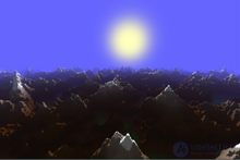
Rendering of a fractal landscape using ray marching
Ray marching is a family of algorithms used in ray casting to find intersections between a ray and a complex object, such as a volumetric dataset or a surface defined by a signed distance function. It is not a rendering method in itself, but it can be incorporated into ray tracing and path tracing, and is used in rasterization to implement screen-space reflections and other effects.
A method called photon mapping traces the paths of photons from a light source to an object, accumulating illumination data that is then used during conventional ray tracing or path tracing. Rendering a scene using only rays traced from the light source to the camera is impractical, although it is closer to reality, since an enormous number of photons would need to be simulated, only a small fraction of which actually reach the camera.
Some authors call conventional ray tracing "backward" ray tracing, since it traces the paths of photons in reverse, from the camera to the light source, while following paths from the light source (as in photon mapping) is called "forward" ray tracing. However, the meaning of these terms is sometimes reversed. Ray tracing that begins from the light source may also be called particle tracing or light tracing, which avoids this ambiguity.
Real-time rendering, including video game graphics, typically uses rasterization but increasingly combines it with ray tracing and path tracing. To provide realistic global illumination, real-time rendering often relies on pre-rendered ("baked") lighting for static objects. For moving objects, it may use a technique called light probes, in which lighting is recorded by rendering omnidirectional views of the scene at selected points in space (often points on a grid to simplify interpolation). These are similar to environment maps, but typically use a very low resolution or an approximation such as spherical harmonics. (Note: Blender uses the term "light probes" for a more general class of pre-recorded lighting data, including reflection maps.)
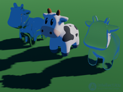
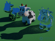
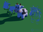
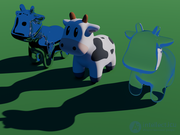
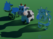
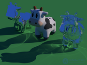

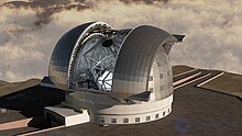
An architectural visualization of the Extremely Large Telescope from 2009, likely created using a combination of technologies
The term "rasterization" (broadly speaking) covers a wide range of techniques used for 2D rendering and real-time 3D rendering. 3D cartoons were rendered using rasterization before ray tracing and path tracing became practical.
A renderer combines rasterization with geometry processing (which is not specific to rasterization) and pixel processing, which computes the RGB color values that are placed into the frame buffer for display.
The main tasks of rasterization (including pixel processing) are:
3D rasterization is usually part of a graphics pipeline, in which the application provides lists of triangles for rendering, and the rendering system transforms and projects their coordinates, determines which triangles are potentially visible in the viewport, and performs the above rasterization and pixel processing tasks before displaying the final result on the screen.
Historically, 3D rasterization used algorithms such as the Warnock algorithm and scanline rendering (also called "scan conversion"), which can handle arbitrary polygons and can rasterize many shapes simultaneously. Although such algorithms are still important for 2D rendering, 3D rendering now typically divides shapes into triangles and rasterizes them separately, using simpler methods.
There are high-performance algorithms for rasterizing 2D lines, including anti-aliased lines, as well as ellipses and filled triangles. An important special case of 2D rasterization is text rendering, which requires careful anti-aliasing and coordinate rounding to avoid distorting letter shapes and to preserve spacing, density, and sharpness.
After projecting 3D coordinates onto the image plane, rasterization is primarily a 2D problem, but the third dimension requires hidden surface removal. Early computer graphics used geometric algorithms or ray casting to remove hidden parts of shapes, or used the painter's algorithm, which sorts shapes by depth (distance from the camera) and renders them back to front. Depth sorting was later superseded by incorporating depth comparison into the scanline rendering algorithm. The z-buffer algorithm performs comparisons indirectly by including a depth, or "z", value in the frame buffer. A pixel is covered by a shape only if that shape's z value is lower (indicating proximity to the camera) than the current z value in the buffer. The z-buffer requires additional memory (an expensive resource at the time of its invention), but it simplifies rasterization code and allows for multiple passes. Memory has since become faster and more abundant, and the z-buffer is now used in almost all real-time rendering.
A drawback of the basic z-buffer algorithm is that each pixel is either fully covered by a single object or filled with the background color, resulting in jagged edges in the final image. Early anti-aliasing approaches addressed this problem by detecting partial pixel coverage by a shape and computing the covered area. The A-buffer (and other subpixel and multisampling techniques) address this problem less precisely but with higher performance. For real-time 3D graphics, it has become common to use sophisticated heuristics (and even neural networks) to perform anti-aliasing.
In 3D rasterization, color is typically determined by a pixel shader or fragment shader, a small program that runs for each pixel. The shader does not have (or cannot have) direct access to the 3D data for the entire scene (this would be very slow and would result in an algorithm resembling ray tracing), and various methods have been developed for rendering effects such as shadows and reflections using only texture mapping and multiple passes.
Older and simpler implementations of 3D rasterization did not support shaders and used simple shading methods, such as flat shading (lighting is calculated once for each triangle, which is then rendered entirely in a single color), Gouraud shading (lighting is calculated using normal vectors defined at the vertices, and then colors are interpolated across each triangle), or Phong shading (normal vectors are interpolated across each triangle, and lighting is calculated for each pixel).
Until recently, Pixar used rasterization to render its animated films. Unlike renderers commonly used for real-time graphics, the Reyes rendering system in Pixar's RenderMan software was optimized for rendering very small (pixel-sized) polygons and included stochastic sampling techniques that are usually associated with ray tracing.
One of the simplest ways to render a 3D scene is to test the intersection of a ray originating at the viewpoint (the "eye" or "camera") with any geometric shape in the scene, repeating this test using a different ray direction for each pixel. This method, called ray casting, was important in early computer graphics and is a fundamental building block for more complex algorithms. Ray casting can be used to render shapes defined by constructive solid geometry (CSG) operations.
Early experiments in ray casting include the work of Arthur Appel in the 1960s. Appel rendered shadows by casting an additional ray from each visible surface point to the light source. He also attempted to render lighting density by casting random rays from the light source to the object and plotting the intersection points (similar to a later technique called photon mapping).
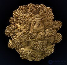
The ray marching method can be used to find the first intersection of a ray with a complex shape, such as this Mandelbulb fractal.
When rendering scenes containing many objects, testing the intersection of a ray with every object becomes very costly. Special data structures are used to speed up this process, allowing large numbers of objects to be quickly excluded (for example, objects behind the camera). These structures are analogous to database indexes for finding relevant objects. The most common are the bounding volume hierarchy (BVH), which stores a precomputed bounding box or sphere for each branch of the object tree, and the kd-tree, which recursively divides space into two parts. Modern GPUs include hardware acceleration for BVH intersection tests. Kd-trees are a special case of binary space partitioning, which was often used in early computer graphics (it can also generate a rasterization order for the painter's algorithm). Octrees, another historically popular method, are still often used for volumetric data.
Geometric formulas suffice to find the intersection of a ray with figures such as spheres, polygons, and polyhedra, but for most curved surfaces there is no analytical solution, or the intersection is difficult to compute precisely using floating-point numbers of limited precision. Sometimes root-finding algorithms, such as Newton's method, can be used. To avoid these complications, curved surfaces are often approximated as meshes of triangles. Volumetric rendering (for example, rendering clouds and smoke) and some surfaces, such as fractals, may require ray marching instead of basic ray casting.
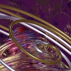
Spiral sphere and Julia, Detail, a computer image created by visual artist Robert W. McGregor using only POV-Ray 3.6 and its built-in scene description language.
Ray casting can be used to render an image by tracing rays of light backward from a simulated camera. After finding the point on a surface where the ray originated, another ray is traced toward the light source to determine whether anything casts a shadow on that point. If not, a reflection model (for example, the Lambertian reflectance model for matte surfaces or the Phong reflection model for glossy surfaces) is used to calculate the probability that a photon arriving from the light source will be reflected toward the camera, and this is multiplied by the brightness of the light to determine the brightness of the pixel. If there are multiple light sources, the brightness contributions of the light sources are summed. For color images, the calculations are repeated for several wavelengths of light (for example, red, green, and blue).
Classical ray tracing (also called Whitted-style or recursive ray tracing) extends this method so that it can render mirrors and transparent objects. If a ray traced backward from the camera originates at a point on a mirror, the reflection formula from geometric optics is used to compute the direction from which the reflected ray came, and another ray is cast backward in that direction. If the ray originates from a transparent surface, rays are cast backward for both the reflected and refracted rays (using Snell's law to compute the refracted direction), and so ray tracing must support a branching «tree» of rays. In simple implementations, a recursive function is called to trace each ray.
Ray tracing usually performs anti-aliasing by averaging several samples for each pixel. It can also use multiple samples for effects such as depth of field and motion blur. If uniformly distributed ray directions or times are used for each of these features, many rays are required, and some aliasing will remain. Cook-style, stochastic, or Monte Carlo ray tracing avoids this problem by using random sampling instead of uniformly distributed samples. This type of ray tracing is usually called distributed ray tracing or distribution ray tracing, because it samples rays from probability distributions. Distributed ray tracing can also render realistic «soft» shadows from large light sources by randomly sampling points on the light source when checking for occlusion, and it can simulate chromatic aberration by sampling several wavelengths from the light spectrum.
Real surface materials reflect a small amount of light in almost every direction, because they have small (or microscopic) bumps and grooves. A distribution ray tracer can simulate this by sampling possible ray directions, which makes it possible to render blurry reflections from glossy and metallic surfaces. However, if this procedure is repeated recursively to simulate realistic indirect lighting, and if more than one sample is taken at each surface point, the ray tree quickly becomes enormous. Another type of ray tracing, called path tracing, handles indirect light more efficiently by avoiding branching and ensures that the distribution of all possible paths from the light source to the camera is sampled in an unbiased way.
Ray tracing was often used to render reflections in animated films until path tracing became the standard for film rendering. Films such as «Shrek 2» and «Monsters University» also used distribution ray tracing or path tracing to precompute indirect lighting for a scene or shot before rendering it using rasterization.
Advances in graphics processing unit technology have made real-time ray tracing possible in games, although it is currently almost always used in combination with rasterization. This makes it possible to create visual effects that are difficult to achieve with rasterization alone, including reflections from curved surfaces and mutually reflective objects, and shadows that are accurate across a wide range of distances and surface orientations. Support for ray tracing is included in the latest graphics APIs used in games, such as DirectX, Metal, and Vulkan
Ray tracing has been used to render simulated black holes and the appearance of objects moving at speeds close to the speed of light, by accounting for the curvature of spacetime and relativistic effects while simulating light rays.
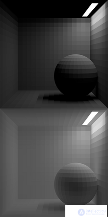
A classic demonstration of radiosity. Surfaces are divided into 16x16 or 16x32 cells. Top: direct light only. Bottom: the radiosity solution (for an albedo of 0.85).
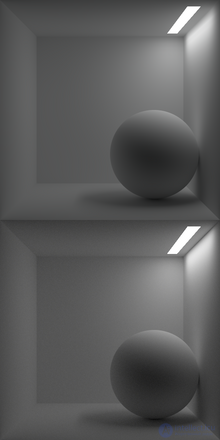
Top: the same scene with a finer radiosity mesh, smoothing the patches during final rendering using bilinear interpolation. Bottom: the scene rendered with path tracing (using the PBRT renderer).
Radiosity (named after the radiometric quantity of the same name) — is a method for rendering objects illuminated by light reflected from rough or matte surfaces. This type of lighting is called indirect light, ambient lighting, or diffuse lighting, and the problem of rendering it realistically is called global illumination. Rasterization and basic forms of ray tracing (other than distribution ray tracing and path tracing) can only approximate indirect light, for example, by adding a uniform amount of «ambient» lighting chosen by the artist. Radiosity methods are also well suited to rendering scenes with area lighting, such as rectangular panels of fluorescent lighting, which are difficult to rasterize and difficult to trace with traditional ray tracing. Radiosity is considered a physically based method, meaning that it aims to simulate the flow of light in an environment using equations and experimental data from physics; however, it often assumes that all surfaces are opaque and perfectly Lambertian, which reduces realism and limits its applicability.
In the original radiosity method (first proposed in 1984), now called classical radiosity, the surfaces and light sources in a scene are divided into pieces called patches, this process is called meshing (this step is what makes it a finite element method). The rendering code must then determine what fraction of the light emitted or diffusely reflected (scattered) by each patch is received by every other patch. These fractions are called form factors or view factors (first used in engineering to model radiative heat transfer). The form factors are multiplied by the albedo of the receiving surface and placed into a matrix. The lighting in the scene can then be expressed as a matrix equation (or, equivalently, a system of linear equations), which can be solved using methods of linear algebra.
Solving the radiosity equation yields the total amount of light emitted and reflected by each patch, which is divided by its area to obtain a value called radiosity, which can be used in rasterization or ray tracing to determine the color of pixels corresponding to visible parts of the patch. For real-time rendering, this value (or, more often, irradiance, which does not depend on the local albedo of the surface) can be precomputed and stored in a texture (called a lightmap) or stored as vertex data for 3D models. This capability has been used in architectural visualization software to enable real-time walkthroughs of a building's interior after the lighting has been calculated.
The large size of the matrices used in classical radiosity (the square of the number of patches) causes problems for realistic scenes. Practical implementations may use Jacobi or Gauss-Seidel iteration, which is equivalent (at least in the Jacobi case) to simulating the propagation of light one bounce at a time until the amount of remaining light (not yet absorbed by surfaces) becomes negligible. The number of iterations (bounces) required depends on the scene rather than on the number of patches, so the total work is proportional to the square of the number of patches (by contrast, solving the matrix equation using Gaussian elimination requires work proportional to the cube of the number of patches). Form factors can be recomputed as needed to avoid storing the full matrix in memory.
Rendering quality is often determined by the size of the patches; for example, accurately rendering shadow edges requires very fine meshes. An important improvement is hierarchical radiosity, which uses a coarser mesh (larger patches) to simulate light transfer between surfaces that are far apart, and adaptively subdivides patches as needed. This makes it possible to use radiosity for much larger and more complex scenes.
Alternative and extended versions of the radiosity method support non-Lambertian surfaces, such as glossy surfaces and mirrors, and sometimes use volumes or «clusters» of objects in addition to surface patches. Stochastic or Monte Carlo radiosity uses random sampling in various ways, for example, sampling incoming light instead of integrating over all patches, which can improve performance but adds noise (this noise can be reduced by using deterministic iterations as a final step, unlike path-tracing noise). Simplified and partially precomputed versions of radiosity are widely used for real-time rendering in combination with techniques such as octree radiosity, which store approximations of the light field
Within the approach known as physically based rendering, path tracing has become the dominant technique for rendering realistic scenes, including effects for films. For example, the popular open-source 3D graphics software Blender uses path tracing in its Cycles renderer. Images produced using path tracing for global illumination tend to be noisier than those produced using radiosity (the main competing algorithm for realistic lighting), but radiosity can be difficult to apply to complex scenes and is prone to artifacts arising from the use of a tessellated representation of illumination
Like distributed ray tracing, path tracing is a form of stochastic or randomized ray tracing that uses Monte Carlo or quasi-Monte Carlo integration. It was proposed and named in 1986 by Jim Kajiya in the same paper as the rendering equation. Kajiya observed that much of the complexity of distributed ray tracing could be avoided if only a single path from the camera were traced at a time (in Kajiya's implementation this «no branching» rule was broken by tracing additional rays from each surface intersection point to randomly chosen points on each light source). Kajiya proposed reducing the noise present in the output images using stratified sampling and importance sampling for making random decisions, such as choosing which ray to follow at each step of the path. Even with these techniques, path tracing would have been impractical for rendering films using the computers available at the time, since the computational cost of generating enough samples to reduce the variance to an acceptable level was too high. «Monster House», the first feature film created entirely using path tracing, was not released until 20 years later.
In its basic form, path tracing is inefficient (requiring too many samples) for rendering caustics and scenes where light enters indirectly through narrow openings. Attempts to address these shortcomings were made in the 1990s. Bidirectional path tracing has similarities to photon mapping, tracing rays from the light source and from the camera separately and then finding ways to connect these paths (but unlike photon mapping, it typically selects new light paths for each pixel rather than using the same cached data for all pixels). Metropolis light transport selects paths by mutating paths that were previously traced, spending more time exploring paths that resemble other «bright» paths, which increases the likelihood of discovering even brighter paths. Multiple importance sampling provides a way to reduce variance when combining samples from more than one sampling method, especially when some samples are much noisier than others.
This later work was generalized and extended in Eric Veach's 1997 doctoral dissertation, which helped increase interest in path tracing within the computer graphics community. The Arnold renderer, first released in 1998, demonstrated that path tracing was practical for rendering frames for films, and that there was demand in the film industry for unbiased, physically based rendering; other commercial and open-source path tracing renderers began to appear. The computational cost was addressed by rapid progress in CPU and cluster performance.
The relative simplicity of path tracing and its nature as a Monte Carlo method (sampling hundreds or thousands of paths per pixel) have made it attractive to implement on the GPU, especially on recent GPUs that support ray-tracing acceleration technology such as Nvidia's RTX and OptiX. However, bidirectional path tracing and Metropolis light transport are harder to implement efficiently on the GPU.
Research on improving path tracing continues. Recent path guiding approaches build approximations of the probability distribution of the light field in each region of space, so that paths can be selected more efficiently. Many techniques have been developed for denoising path tracing output, reducing the number of paths needed to achieve acceptable quality, at the risk of losing some detail or introducing small-scale artifacts that are more objectionable than noise; neural networks are now widely used for this purpose.
Neural rendering — is a rendering method that uses artificial neural networks. Neural rendering includes image-based rendering techniques, which are used to reconstruct 3D models from 2-dimensional images. One such technique is photogrammetry, a method in which a set of images taken from different angles of an object is converted into a 3D model. There have also been recent developments in generating and rendering 3D models from text and rough sketches, notably by Nvidia, Google, and various other companies.
1. Rasterization – is the conversion of an image described in vector format into pixels or dots, for output to a display or printer. It geometrically projects objects onto the image plane without taking optical effects into account.
One can distinguish between algorithms for rasterizing two-dimensional scenes and scanline algorithms, which operate in a «line by line» mode. Suppose we need to produce an image with a resolution of 1024×1080. The program draws an imaginary line through each pixel, calculating which polygons lie along the path of this line and computes the required pixel color, depending on which textures and colors have been assigned to the polygons that intersected the path of this imaginary line. The next pixel is then taken, then the next – and so on to the end. The advantage of this method is that there is no need to transfer the coordinates of all vertices from main memory to working memory — only the vertices that fall within the visible area. Each vertex is read into working memory only once, which significantly increases rendering speed.
The main problem with this method is separating visible polygons from hidden ones. In the first generations of such renderers, the process of computing polygons began with the point farthest from the viewer, and each new polygon painted over the previous one. This approach is far from ideal because of the large number of unnecessary operations involved. To solve this problem, a Z-buffer is used. The program computes all the polygons lying along the path of the imaginary line and assigns each polygon a Z – value depending on its distance from the screen. When it comes time to render, only the polygons with the smallest Z-value are computed – the others are simply discarded.
2. Ray casting (from the English «ray casting»). The scene is treated as being observed from a specific point. Rays are directed from the viewpoint toward the objects of the scene, and these rays are used to determine the color of a pixel on the two-dimensional screen. In doing so, the rays stop propagating (unlike in the backward ray-tracing method) once they reach some object in the scene or its background. It is possible to use various very simple methods to add optical effects. The perspective effect arises naturally if the rays are cast at an angle that depends on the position of the pixel on the screen and the maximum angle of the camera lens.
3. Ray tracing (from the English «ray tracing») is akin to the ray casting method. Rays are directed from the viewpoint toward the objects of the scene, and these rays are used to determine the color of a pixel on the two-dimensional screen. But in this case the ray does not stop propagating; instead it splits into three components, each of which contributes to the color of the pixel on the two-dimensional screen: reflected, shadow, and refracted. The number of such component splits determines the tracing depth and affects the quality and realism of the image.
image.
4. Path tracing contains a similar principle of ray propagation tracing, but this method is the closest to the physical laws of light propagation. It is also the most resource-intensive.
Modern software usually combines several techniques in order to obtain a sufficiently high-quality and photorealistic image at an acceptable computational cost.
The implementation of a realistic renderer always contains some basic element of physical modeling or emulation — some computations that resemble or abstract an actual physical process.
The term «physically based» indicates the use of physical models and approximations that are more general and widely accepted beyond rendering. A specific set of related methods has gradually become established within the rendering community.
The basic concepts are relatively simple, but do not lend themselves to computation; and a single elegant algorithm or approach has proven elusive for more universal renderers. To satisfy the requirements of reliability, accuracy, and practicality, an implementation will represent a complex combination of various methods.
Research in the field of rendering is concerned both with adapting scientific models and with applying them effectively.
The mathematics used in rendering includes: linear algebra, calculus, numerical mathematics, signal processing, and Monte Carlo methods.
This is a key academic/theoretical concept in rendering. It serves as the most abstract formal expression of the non-perceptual aspect of rendering. All more complete algorithms can be regarded as solutions to particular formulations of this equation.

Meaning: at a given position and direction, the outgoing light (L o ) is the sum of the emitted light (L e ) and the reflected light. The reflected light is the sum of the incoming light (L i ) from all directions, multiplied by the surface reflectance and the angle of incidence. By connecting outgoing light to incoming light through the point of interaction, this equation denotes the entire «transport of light» – all the movement of
продолжение следует...
Часть 1 Rendering (Computer Graphics)
Часть 2 Hardware - Rendering (Computer Graphics)

Comments