
Lecture
In vector computer graphics, computer-aided design systems, and geographic information systems, a geometric primitive (or prim) is the simplest (i.e., "atomic" or irreducible) geometric shape that a system can handle (draw, store). Sometimes the subroutines that draw the corresponding objects are also called "geometric primitives." The most "primitive" primitives are the point and the line segment, which were all that existed in early vector graphics systems.
In constructive solid geometry (stereometry), primitives refer to simple geometric solids such as the cube, cylinder, sphere, cone, pyramid, and torus.
Modern 2D computer graphics systems can operate with primitives such as lines (segments of straight lines, circles, or more complex curves such as Bezier curves), as well as shapes (triangles, rectangles, arbitrary polygons, circles).
The usual set of two-dimensional primitives includes lines, points, and polygons, although some people prefer to consider triangles as primitives because every polygon can be constructed from triangles. All other graphical elements are built from these primitives. In three dimensions, triangles or polygons positioned in three-dimensional space can be used as primitives for modeling more complex three-dimensional shapes. In some cases, curves (such as Bezier curves, circles, etc.) may be considered primitives; in other cases, curves are complex shapes constructed from a multitude of straight primitive shapes.
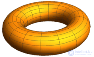
3D torus
In 3D applications, the basic geometric figures and shapes differ from those listed above. Among them:
3D applications may have an extended list of primitives with more complex shapes that come bundled with the application. For example, a teapot is a primitive in 3D Studio Max.
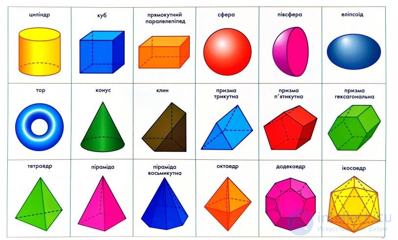
The set of geometric primitives is based on the dimensionality of the represented area:
In GIS, the terrain surface is often colloquially called "2 1/2-dimensional," since only the upper surface needs to be represented. Thus, height can be conceptualized as a property of a scalar field, or a function of two-dimensional space, which gives it a number of data-modeling efficiencies compared to true three-dimensional objects. The shape of any of these dimensions greater than zero consists of an infinite number of individual points. Since digital systems are finite, only a sampled set of points on the shape can be stored. Thus, vector data structures typically represent geometric primitives using strategic sampling, organized into structures that make it easier for software to interpolate the remaining part of the shape during analysis or display using computational geometry algorithms.
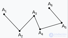
A simple polyline

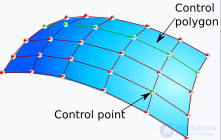
NURBS surface
Graphics processing units use hardware acceleration to render primitives such as points and triangles, typically together with textures and shaders.
Texture (texture mapping) is a way of giving a surface 3D detail — a polygon's color, texture, gloss, matte finish, and other physical properties (most often to simulate some natural material, such as paper, wood, stone, metal, and so on).
Shader — a program for one of the stages of the graphics pipeline, used in three-dimensional graphics to determine the final parameters of an object or image. It may include an arbitrarily complex description of light absorption and scattering, texture mapping, reflection and refraction, shading, surface displacement, and post-processing effects.
Programmable shaders are flexible and efficient. Surfaces that appear complex can be rendered using simple geometric shapes. For example, shaders can be used to draw the surface of three-dimensional ceramic tile on a perfectly flat surface.
Modern 3D accelerators typically accept a set of triangles in the form of a triangle strip.
Over the history of geographic information systems, many vector structures and data formats have been developed, but they share a fundamental basis of storing a core set of geometric primitives to represent the location and extent of geographic phenomena. The location of points is almost always measured in a standard coordinate system based on the Earth, whether a spherical geographic coordinate system (latitude/longitude) or a planar coordinate system such as the Universal Transverse Mercator projection. They also share the need to store a set of attributes for each geographic feature alongside its shape; traditionally this has been achieved using data models, data formats, and even relational database software.
Early vector formats, such as POLYVRT, ARC/INFO Coverage, and the Esri shapefile, support a basic set of geometric primitives — points, polylines, and polygons — only in two-dimensional space, and the latter two only with straight-line interpolation. TIN data structures were also added to represent terrain surfaces as triangular meshes. Since the mid-1990s, new formats have been developed that extend the range of available primitives, largely standardized by the Open Geospatial Consortium's Simple Features specification. Common extensions to geometric primitives include: three-dimensional coordinates for points, lines, and polygons; a fourth "dimension" to represent a measured attribute or time; curved segments in lines and polygons; text annotation as a form of geometry; and polygon meshes for three-dimensional objects.
Often the representation of the shape of a real-world phenomenon may have a different (usually lower) dimension than the phenomenon being represented. For example, a city (a two-dimensional region) may be represented as a point, and a road (a three-dimensional volume of material) may be represented as a line. This dimensional generalization correlates with tendencies in spatial cognition. For example, a question about the distance between two cities implies a conceptual model of cities as points, while giving directions that involve moving "up," "down," or "along" a road implies a one-dimensional conceptual model. This is often done for the sake of data efficiency, visual simplicity, or cognitive efficiency, and is acceptable as long as the distinction between the representation and the thing represented is understood, but it can cause confusion if users of the information assume that the digital form is a perfect representation of reality (i.e., believe that roads are actually lines).
In CAD or 3D modeling software, the interface may provide the user with the ability to create primitives that can be further modified through editing. For example, in box-modeling practice, the user will start with a cuboid, then use extrusion and other operations to create the model. In this usage, a primitive is simply a convenient starting point rather than a fundamental unit of modeling.
A 3D package may also include a list of extended primitives, which are more complex shapes included in the package. For example, a teapot is listed as a primitive in 3D Studio Max.

Comments