
Lecture
In computer graphics, reflection mapping or environment mapping is an efficient image-based lighting method for approximating the appearance of a reflective surface by means of a precomputed texture . The texture is used to store an image of the distant environment surrounding the rendered object.
Several methods have been used to store the surrounding environment. The first method was sphere mapping , in which a single texture contained the image of the environment as reflected on a spherical mirror . It has been almost entirely superseded by cube mapping , in which the environment is projected onto the six faces of a cube and stored as six square textures, or unfolded into six square regions of a single texture. Other projections that have some superior mathematical or computational properties include paraboloid mapping, pyramid mapping, octahedral mapping, and HEALPix mapping .
Reflection mapping is one of several approaches to rendering reflections , alongside, for example, screen-space reflections or ray tracing , which computes an exact reflection by tracing a ray of light and following its optical path . The color of the reflection used in computing the shading at a pixel is determined by computing the reflection vector at a point on the object and matching it to a texel on the environment map. This method often produces results that are visually similar to those obtained by ray tracing, but is less computationally expensive, since the reflected brightness value is obtained by computing the angles of incidence and reflection followed by a texture lookup, rather than by tracing a ray through the scene geometry and computing the ray's brightness, which simplifies the workload on the GPU .
In most cases, however, a mapped reflection is only an approximation of a real reflection. Environment mapping relies on two assumptions that are rarely satisfied:
Environment mapping is generally the fastest method for rendering a reflective surface. To further increase rendering speed, the renderer may compute the position of the reflected ray at each vertex. The position is then interpolated across the polygons to which the vertex is attached. This eliminates the need to recompute the reflection direction for each pixel.
If normal mapping is used, each polygon has multiple face normals (the direction a given point on the polygon faces), which can be used together with the environment map to create a more realistic reflection. In this case, the angle of reflection at a given point on the polygon will take the normal map into account. This method is used to make a flat surface appear textured, such as corrugated metal or brushed aluminum. 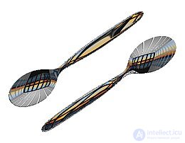
An environment texture applied to spoon models to create the illusion that they are reflecting the surrounding world.
Sphere mapping represents the sphere of incident lighting as it would appear reflected in a reflective sphere viewed through an orthographic camera. The texture image can be created by approximating this ideal setup, using a «fisheye» lens, or by pre-rendering a scene with sphere mapping.
Sphere mapping suffers from limitations that reduce the realism of the resulting renders. Because sphere maps are stored as azimuthal projections of the environments they represent, a sharp point of singularity (the «black hole» effect) is visible in the reflection on the object, where the colors of texels at or near the edge of the map are distorted due to insufficient resolution to accurately represent the points. Sphere mapping also wastes pixels that lie within the square but outside the circle.
The artifacts of sphere mapping are so severe that it is effective only for viewpoints close to the viewpoint of the virtual orthographic camera.
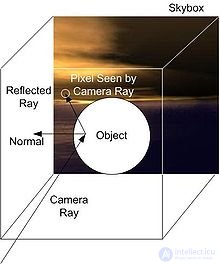
Diagram depicting the apparent reflection provided by cube mapping. The map is effectively projected onto the surface from the viewer's point of view. Highlights that, with ray tracing, would be obtained by tracing a ray and determining the angle formed with the normal, can be «faked» if they are manually drawn into the texture field (or if they already appear there depending on how the texture map was obtained), from where they will be projected onto the mapped object along with the rest of the texture detail.
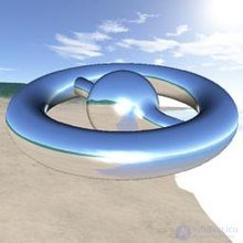
Example of a three-dimensional model using cube reflection
Cube mapping and other polyhedron mappings solve the problem of the severe distortion of sphere maps. If cube maps are made and filtered correctly, they have no visible seams and can be used regardless of the viewpoint of the often virtual camera that captured the map. Cube and other polyhedron maps have since replaced sphere maps in most computer graphics applications, except for image-based lighting acquisition . Image-based lighting can be performed using parallax-corrected cube maps.
Typically, cube mapping uses the same skybox that is used in outdoor rendering. Cube-mapped reflection is performed by determining the vector from which the object is viewed. This camera ray is reflected relative to the surface normal at the point where the camera vector intersects the object. This produces a reflected ray , which is then passed to the cube map to obtain a texel that provides the brightness value used in the lighting calculation. This creates the effect of the object being reflective.
HEALPix environment mapping is similar to other polyhedron mappings, but can be hierarchical, thereby providing a unified framework for generating polyhedra that better approximate a sphere. This allows distortion to be reduced at the cost of increased computation.
In 1974, Edwin Catmull created an algorithm for «rendering images of two-dimensional surface patches» , which worked directly with their mathematical definition. Further improvements were explored and documented by Bui Tuong Phong in 1975, and later by James Blinn and Martin Newell , who developed environment mapping in 1976; these developments, which refined Catmull's original algorithms, led them to conclude that «these generalizations lead to improved methods for generating patterns and textures».
Gene Miller experimented with sphere environment mapping in 1982 at MAGI .
Wolfgang Heidrich introduced paraboloid mapping in 1998.
Emil Praun introduced octahedral mapping in 2003.
Mauro Steigleder introduced pyramid mapping in 2005.
Tien-Tsin Wong et al. introduced the existing HEALPix mapping for rendering in 2006.

Comments