
Lecture
The discrepancy between spatial objects and flat images is eliminated by the design of projecting three-dimensional objects onto a two-dimensional projection plane. The projection of a three-dimensional object, represented as a set of points, is constructed using straight projecting rays, called projectors, which emanate from the center of projection, pass through each point of the object, and, intersecting the picture plane, form a projection. (Fig. 3.2)
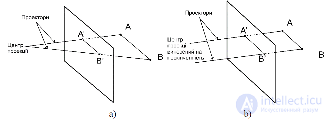
Fig. 3.2 – Segment AB and its projection A'B': a – central; b – parallel.
Since the projection of a segment is itself a segment, it is sufficient to project only the endpoints. The class of projections defined in this way is known as planar geometric projections, since the projecting in this case is performed onto a plane rather than onto a curved surface, and straight lines rather than curves are used as projectors. In contrast to them, many cartographic projections are either non-planar or non-geometric.
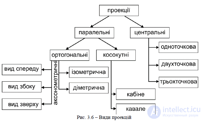
Planar geometric projections, which we will henceforth simply call projections, can be divided into two main classes: central and parallel. The distinction between them is determined by the relationship between the center of projection and the projection plane. If the distance between them is finite, the projection is central; if it is infinite, the projection is parallel. When describing a central projection, we explicitly specify its center of projection, whereas when defining a parallel projection, we specify the direction of projection.
Central projection produces a visual effect similar to that produced by photographic systems or the human visual system, and is therefore used when a certain degree of realism is required. This effect is known as perspective foreshortening: the size of the central projection of an object decreases as the projection plane approaches the center of projection. This means that, although central projection is realistic, it is unsuitable for representing the exact shape and dimensions of an object: distance information cannot be obtained from the projection; angles are preserved only on those faces of the object that are parallel to the projection plane; and the projections of parallel lines are generally not parallel.
Parallel projection produces a less realistic image, since there is no perspective foreshortening, although different constant foreshortenings may occur along each of the axes. The projection preserves true dimensions (up to a scalar factor), and parallel lines remain parallel. As with central projection, angles are preserved only on those faces of the object that are parallel to the projection plane.
The central projections of any set of parallel lines not parallel to the projection plane will converge at a vanishing point. There is an infinite number of vanishing points. If the set of lines is parallel to one of the principal coordinate axes, its vanishing point is called a principal vanishing point. There are only three such points, corresponding to the three coordinate axes. If, for example, the projection plane intersects only the 𝑧 axis and is therefore perpendicular to it, then only on this axis will the principal vanishing point lie, since lines parallel to both the 𝑦 and 𝑥 axes are also parallel to the projection plane and therefore have no vanishing point.
Central projections are classified according to the number of principal vanishing points they have, and consequently, according to the number of coordinate axes intersected by the projection plane.
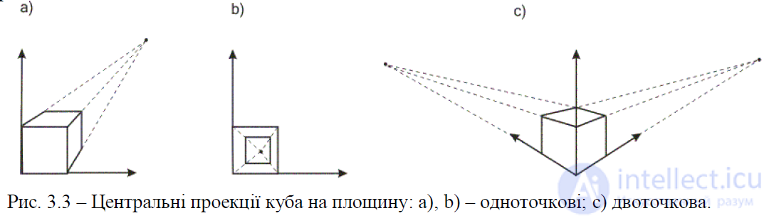
Fig. 3.3 – Central projections of a cube onto a plane: a), b) – one-point; c) – two-point.
Two-point central projection is widely used in design and in advertising images, in which vertical lines are projected as parallel and therefore do not converge. Three-point central projections are almost never used, firstly because they are difficult to construct, and secondly because they add little in terms of realism compared to two-point projection.
Parallel projections are divided into two types depending on the relationship between the direction of projection and the normal to the projection plane. In orthographic parallel projections these directions coincide, while in oblique parallel projections they do not. That is, in orthographic projections the direction of projection is the normal to the projection plane.
The most common types of orthographic projections are the front view, top view (plan), and side view (Fig. 3.4), in which the picture plane is perpendicular to the principal coordinate axes, which consequently coincide with the direction of projection. Distances and angles can be measured from these projections.
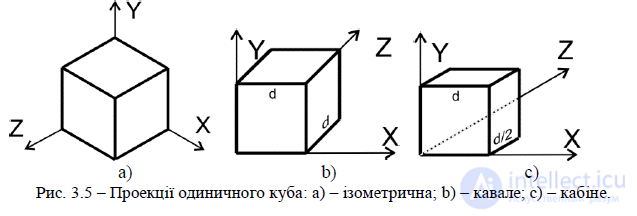
Fig. 3.5 – Projections of a unit cube: a) – isometric; b) – cavalier; c) – cabinet.
Fig. 3.4 – Orthographic projections of a truncated cube
Axonometric orthographic projections use projection planes that are not perpendicular to the principal coordinate axes, so that several sides of the object are shown at once, as is also the case with central projection. However, in axonometry the foreshortening is constant, whereas for central projection it depends on the distance from the center of projection. In axonometric projection, the parallelism of lines is preserved while angles are altered; distances can be measured along the principal coordinate axes (generally with different scale factors).
A frequently used axonometric projection is isometric projection (Fig. 3.5-a). In this case, the normal to the projection plane (and hence the direction of projection) makes equal angles with each of the principal coordinate axes. Isometric projection has the following property: all three principal coordinate axes are foreshortened equally. This makes it possible to take measurements along the direction of the axes using the same scale (hence the name ISO, meaning equal).
Oblique projections. The projection plane is perpendicular to a principal coordinate axis. The side of the object parallel to this plane is projected in such a way that angles and distances can be measured. Projecting the other sides also allows linear (but not angular) measurements to be taken along the principal axes.
Two important types of oblique projections are the cavalier projection (Fig. 3.5-b) – cavalier (in the domestic literature, horizontal oblique isometry – military perspective) and the cabinet projection (Fig. 3.5-c) – cabinet (frontal oblique dimetry – cabinet projection).
In cavalier projection, the direction of projection generally makes a 45° angle with the projection plane. Distances along each axis are laid off equally, which allows measurements to be taken but distorts the representation of the object's true shape.
Cabinet projection has a direction of projection that makes an angle of 𝑎𝑟𝑐𝑐𝑡𝑔(1/2) with the projection plane. In this case, segments perpendicular to the projection plane, after projection, are reduced to half their actual length. Cabinet projections are more realistic than cavalier projections, since a foreshortening factor of 1/2 agrees better with our visual experience.

Comments