
Lecture
A polygon mesh (also called a "mesh" from the English polygon mesh) is a collection of vertices, edges, and faces that define the shape of a polyhedral object in three-dimensional computer graphics and volumetric modeling. The faces are usually triangles, quadrilaterals, or other simple convex polygons, since this simplifies rendering, but meshes may also consist of more general concave polygons [clarify], or polygons with holes.
A polygon mesh is a collection of interconnected flat polygons. The drawback of this method is its approximate nature.
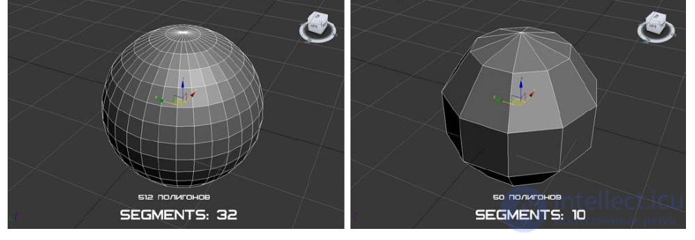
Fig. 2.3 – polygonal approximation of a sphere in 3ds Max.
The degree of approximation can be increased by increasing the number of polygons. But
this leads to additional memory costs and running time for algorithms working with
such a representation, Fig. 2.3
The study of polygon meshes is a large subfield of computer graphics and geometric modeling. Many operations performed on meshes may include Boolean algebra, smoothing, simplification, and many others. Different representations of polygon meshes are used for different purposes and applications. To transmit polygon meshes over a network, network representations such as «streaming» and «progressive» meshes are used. Volumetric meshes differ from polygon meshes in that they explicitly represent both the surface and the volume of a structure, whereas polygon meshes explicitly represent only the surface, not the volume. Since polygon meshes are widely used in computer graphics, algorithms for ray tracing, collision detection, and rigid body dynamics have been developed for them.
The mathematical equivalent of polygon meshes — unstructured meshes — are studied using methods of combinatorial geometry.
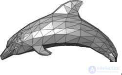
An example of a polygon mesh depicting a dolphin.
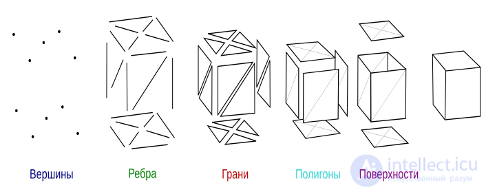
Polygon meshes consist of edges, vertices, and polygons. Vertices are connected by edges, and polygons are treated as sequences of edges or vertices. A mesh can be represented in several different ways.
2.3.1. Explicit definition of polygons
Each polygon is represented as a list of the coordinates of its vertices: 𝑃=((𝑥1,𝑦1,𝑧1),(𝑥2,𝑦2,𝑧2),…(𝑥𝑛,𝑦𝑛,𝑧𝑛)).
The vertices are given in the order in which they are encountered during traversal. All consecutive vertices of the polygon, as well as the first and last, are connected by edges. For a single polygon this method of recording is efficient, but for a polygon mesh it results in a large loss of memory due to the duplication of coordinate information for shared vertices. Moreover, there is no explicit description of shared vertices. For example, finding all polygons that share a given vertex requires comparing the coordinate triples of one polygon's vertices with the coordinate triples of other polygons' vertices.
2.3.2. Defining polygons using pointers to a vertex list
Each node of the polygon mesh is stored only once in the vertex list 𝑉=((𝑥1,𝑦1,𝑧1),(𝑥2,𝑦2,𝑧2),...
This representation makes it possible to save a significant amount of memory. In addition, vertex coordinates can be easily changed. However, it is still not easy to find polygons with shared edges
2.3.3. Explicit definition of edges
This representation includes a list of vertices 𝑉. A polygon is treated as a set of pointers to elements of the edge list, in which each edge appears only once. Each edge in the edge list points to the two vertices in the vertex list that define that edge, as well as to one or two polygons to which that edge belongs. Thus, we describe a polygon as
P=(E1,....En) and an edge, for example, as E=(V1, V2, P1, P2).
If an edge belongs to only one polygon, then P1 or P2 is empty.
A polygon mesh is displayed by traversing not all the polygons, but all the edges. Individual polygons are also displayed fairly simply in this case
Objects created using polygon meshes must store various types of elements, such as vertices, edges, faces, polygons, and surfaces. In many cases only vertices, edges, and either faces or polygons are stored. A renderer may support only three-sided faces, so polygons must be built from a set of them, as shown in Fig. 1. However, many renderers support polygons with four or more sides, or are able to triangulate polygons into triangles on the fly, making it unnecessary to store the mesh in triangulated form. Also, in some cases, such as head modeling, it is desirable to be able to create both three-sided and four-sided polygons.
A vertex is a position together with other information, such as color, normal vector, and texture coordinates. An edge is a connection between two vertices. A face is a closed set of edges, in which a triangular face has three edges and a quadrilateral face has four. A polygon is a set of coplanar (lying in the same plane) faces. In systems that support multi-sided faces, polygons and faces are equivalent. However, most rendering hardware supports only faces with three or four sides, so polygons are represented as a set of faces. Mathematically, a polygon mesh can be represented as an unstructured mesh, or an undirected graph, with added properties of geometry, shape, and topology.
Surfaces, more commonly called smoothing groups, are useful but not required for grouping smooth areas. Imagine a cylinder with caps, such as a tin can. For smooth shading of the sides, all normals must point horizontally outward from the center, whereas the normals of the caps must point in the +/-(0,0,1) directions. If rendered as a single, Phong-shaded surface, the vertices at the seams would have incorrect normals. Therefore, a way is needed to define where to stop smoothing in order to group the smooth parts of the mesh, just as polygons group three-sided faces. As an alternative to providing surfaces/smoothing groups, a mesh may contain other information for calculating the same data, such as a crease angle (polygons with normals above this threshold are either automatically treated as separate smoothing groups, or some technique such as splitting or beveling is applied to the edge between them). Also, polygon meshes with very high resolution are less prone to the problems that smoothing groups are meant to solve, since their polygons are so small that the need for them disappears. In addition, an alternative exists in simply disconnecting the surfaces themselves from the rest of the mesh. Renderers do not attempt to smooth edges between non-adjacent polygons.
A polygon mesh format may define other useful data as well. Groups may be defined that designate individual elements of the mesh and are useful for establishing individual subobjects for skeletal animation or individual subjects for non-skeletal animation. Materials are usually defined, allowing different parts of the mesh to use different shaders when rendering. Most mesh formats also provide for UV coordinates, which are a separate two-dimensional representation of the polygon mesh, «unwrapped» to show which part of the two-dimensional texture is applied to different polygons of the mesh.
Polygon meshes can be represented in many ways, using different methods of storing vertices, edges, and faces. These include:
Each of these representations has its own advantages and disadvantages
The choice of data structure is determined by the application, the required performance, the size of the data, and the operations to be performed. For example, it is easier to work with triangles than with general polygons, especially in computational geometry. For certain operations it is necessary to have fast access to topological information, such as edges or neighboring faces; this requires more complex structures, such as the «winged-edge» representation. Hardware rendering requires compact, simple structures; therefore, low-level APIs such as DirectX and OpenGL typically include a corner table (triangle fan).
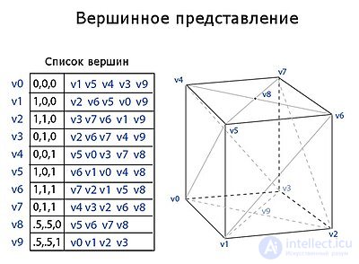
Vertex representation describes an object as a set of vertices connected to other vertices. This is the simplest representation, but it is not widely used, since information about faces and edges is not explicitly expressed. Therefore, all the data must be traversed to generate a face list for rendering. In addition, operations on edges and faces are not easily performed.
However, VR meshes benefit from low memory usage and efficient transformation. Figure 2 shows an example of a parallelepiped depicted using a VR mesh. Each vertex indexes its neighboring vertices. Note that the last two vertices, 8 and 9, at the top and bottom of the parallelepiped, have four connected vertices rather than five. The core system must be able to handle an arbitrary number of vertices connected to any given vertex.
For a more detailed description of VR meshes, see Smith (2006) (in English).
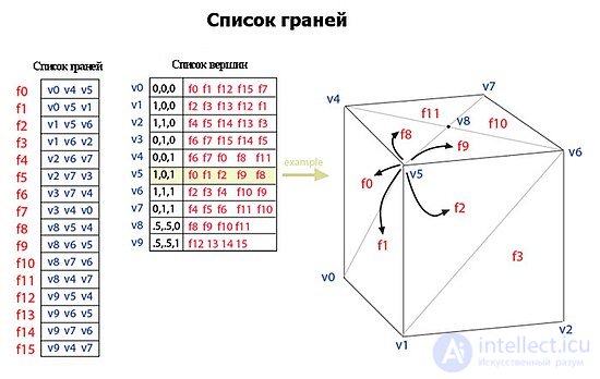
A mesh using a face list represents an object as a set of faces and a set of vertices. This is the most widely used representation, being the input data typically accepted by modern graphics hardware.
The face list is better for modeling than the vertex representation in that it allows explicit lookup of a face's vertices, and of the faces surrounding a vertex. Figure 3 shows an example of a parallelepiped represented as a mesh using a face list. Vertex v5 is highlighted to show the faces that surround it. Note that in this example each face necessarily has 3 vertices. However, this does not mean that every vertex has the same number of surrounding faces.
For rendering, a face is usually sent to the GPU as a set of vertex indices, and the vertices are sent as position/color/normal structures (only the position is shown in the figure). Therefore, changes to shape, but not to geometry, can be dynamically updated simply by resending the vertex data without updating the face connectivity.
Modeling requires easy traversal of all structures. With a mesh using a face list, it is very easy to find a face's vertices. Also, the vertex list contains a list of all faces connected to each vertex. Unlike the vertex representation, both faces and vertices are explicitly represented, so finding neighboring faces and vertices is constant in time. However, edges are not explicitly defined, so a search is still needed to find all the faces surrounding a given face. Other dynamic operations, such as splitting or merging a face, are also complex with a face list.
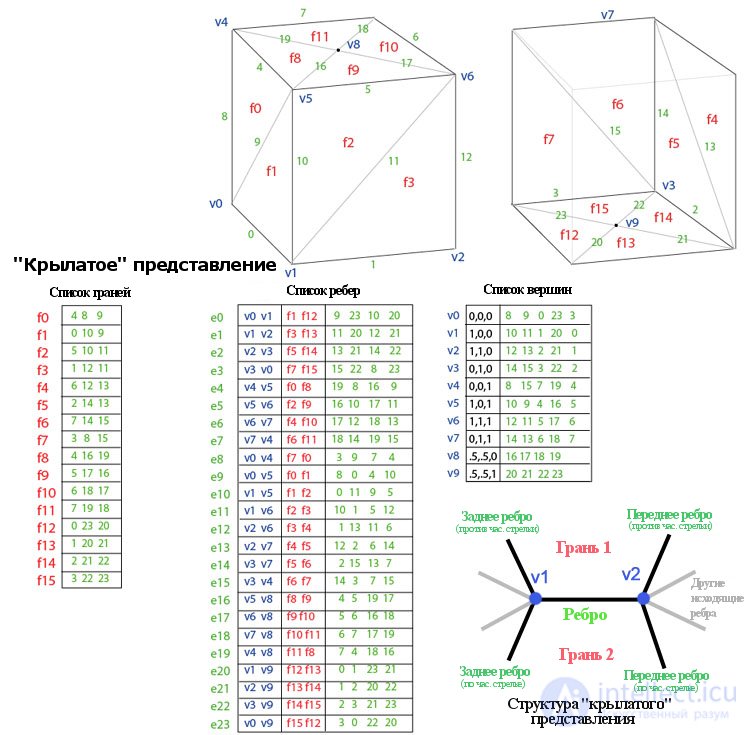
Introduced by Bruce Baumgart in 1975, the «winged-edge» representation explicitly represents the vertices, faces, and edges of a mesh. This representation is widely used in modeling programs to provide the highest flexibility for dynamically changing mesh geometry, because split and merge operations can be performed quickly. Their main drawback is high memory requirements and increased complexity due to containing many indices.
The «winged-edge» representation solves the problem of traversing from edge to edge and provides an ordered set of faces around an edge. For any given edge, the number of outgoing edges can be arbitrary. To simplify this, the «winged-edge» representation provides only the four nearest edges, clockwise and counterclockwise, at each end of the edge. Other edges can be traversed incrementally. Therefore, the information for each edge resembles a butterfly, which is why the representation is called «winged». Figure 4 shows an example of a parallelepiped in the «winged-edge» representation. The complete data for an edge consist of two vertices (endpoints), two faces (one on each side), and four edges (the «wings» of the edge).
Rendering the «winged-edge» representation with graphics hardware requires generating a list of face indices. This is usually done only when the geometry changes. The «winged-edge» representation is ideally suited for dynamic geometry, such as subdivision surfaces and interactive modeling, since mesh changes can occur locally. Traversal around the mesh, which can be useful for collision detection, can be performed efficiently.
See Baumgart (1975) for details
| Operation | Vertex representation | Face list | «Winged-edge» representation | |
|---|---|---|---|---|
| V-V | All vertices around a vertex | Explicit | V → f1, f2, f3, … → v1, v2, v3, … | V → e1, e2, e3, … → v1, v2, v3, … |
| E-F | All edges of a face | F(a, b,c) → {a, b}, {b, c}, {a, c} | F → {a, b}, {b, c}, {a, c} | Explicit |
| V-F | All vertices of a face | F(a, b,c) → {a, b,c} | Explicit | F → e1, e2, e3 → a, b, c |
| F-V | All faces around a vertex | Pair search | Explicit | V → e1, e2, e3 → f1, f2, f3, … |
| E-V | All edges around a vertex | V → {v, v1}, {v, v2}, {v, v3}, … | V → f1, f2, f3, … → v1, v2, v3, … | Explicit |
| F-E | Both faces of an edge | List comparison | List comparison | Explicit |
| V-E | Both vertices of an edge | E(a, b) → {a, b} | E(a, b) → {a, b} | Explicit |
| Flook | Find a face with given vertices | F(a, b,c) → {a, b,c} | Intersection of sets v1,v2,v3 | Intersection of sets v1,v2,v3 |
| Memory size | V*avg(V,V) | 3F + V*avg(F,V) | 3F + 8E + V*avg(E,V) | |
| Example with 10 vertices, 16 faces, 24 edges: | ||||
| 10 * 5 = 50 | 3*16 + 10*5 = 98 | 3*16 + 8*24 + 10*5 = 290 | ||
| Figure 5: summary of mesh representation operations |
In the table above, "explicit" indicates that the operation can be performed in constant time, since the direct data is stored; "list comparison" indicates that performing the operation requires comparing two lists; and "pair search" indicates that a search of two indices must be performed. The notation avg(V,V) denotes the average number of vertices connected to a given vertex; avg(E,V) denotes the average number of edges connected to a given vertex, and avg(F,V) — the average number of faces connected to a given vertex.
The notation «V → f1, f2, f3, … → v1, v2, v3, …» shows that performing the operation requires traversing several elements. For example, to obtain «all vertices around a given vertex V» using the face list, one must first find the faces around the given vertex V using the vertex list. Then, from these faces, using the face list, find the vertices around them. Note that the «winged-edge» representation stores almost all information explicitly, and other operations always traverse the edge first to obtain additional information. The vertex representation is the only representation that explicitly stores the neighboring vertices of a given vertex.
As the complexity of the representations increases (left to right in the summary), the amount of information stored explicitly grows. This provides more direct, constant-time access for traversal and topology of various elements, but at the cost of increased memory usage for properly storing the indices.
As a general rule, meshes using a face list are used whenever an object needs to be rendered with hardware that does not change the geometry (connectivity), but can deform or transform it (vertex positions), for example in rendering static or transformable objects in real time. The «winged-edge» representation is used when the geometry changes, for example in interactive modeling packages or for computing subdivision surfaces. The vertex representation is ideal for efficient, extensive changes in geometry or topology, as long as hardware rendering is not important.
Streaming meshes store faces in an ordered but independent manner, so that the mesh can be transmitted in parts. The order of the faces can be spatial, spectral, or based on other properties of the mesh. Streaming meshes allow very large meshes to be rendered even while they are still loading.
Progressive meshes transmit vertex and face data with an increasing level of detail. Unlike streaming meshes, progressive meshes provide the overall shape of the whole object, but at a low level of detail. Additional data, new edges and faces, progressively increase the detail of the mesh.
Normal meshes transmit gradual changes to a mesh as a set of normal displacements from a base mesh. Using this technique, a series of textures represents the desired incremental changes. Normal meshes are compact, since only a single scalar value is needed to express a displacement. However, the technique requires a series of complex transformations to create the displacement textures.
Polygon meshes can be stored in a variety of file formats:

Comments