
Lecture
One of the most widespread and illustrative methods for producing realistic images is the ray tracing method (RayTracing), which makes it possible to construct photorealistic images of complex scenes while accounting for effects such as reflection and refraction.
Let us consider how a real image is formed. From each light source we emit a bundle of rays in all directions and mentally follow them. When a ray strikes the boundary of an object, if the object is neither reflective nor refractive, the ray's trajectory is terminated; otherwise, we emit reflected and refracted rays from the point of incidence and trace them, along with all rays they generate.
For new rays, three possible outcomes exist for further interaction with the objects of the scene:
all calculations are discarded, since the ray makes no contribution to forming the
image.
of the corresponding image pixel.
illumination calculation is performed, a new ray is constructed, and the process continues until all
rays arrive at scenario 1 or 2.
The process described above is called forward ray tracing. It makes it possible to obtain an image of the scene, but it requires enormous computational costs. The main drawback of this approach is that most of the rays considered never reach the eye.
Figure 7 illustrates the forward ray tracing method
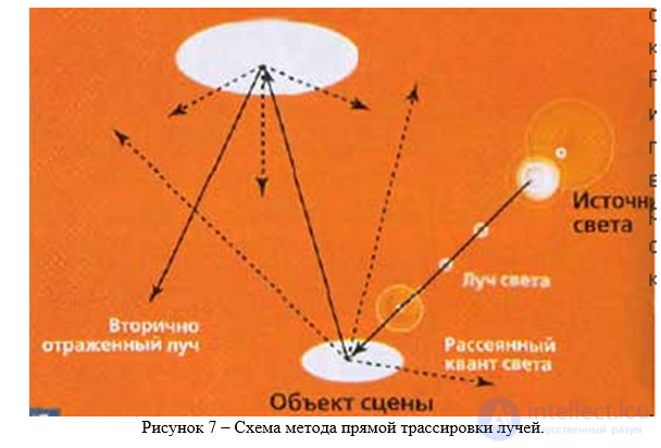
Figure 7 – Diagram of the forward ray tracing method.
As a rule, a probabilistic modification of the method is applied — in the simulation, individual quanta are emitted in a random direction from the light source, and the more quanta that are calculated, the more complete the resulting picture of illumination will be. Using a physically accurate model of light propagation makes it possible to obtain a realistic illumination picture that accounts for secondary illumination and other effects, but this approach requires a large volume of computation. For each quantum, a great many complex operations must be performed — if only to find the point of collision with the first object. This is especially true when there are many objects in the scene and each is represented by a large collection of triangles.
The forward photon tracing method is fully universal thanks to its illumination model, which closely approximates reality. However, it does not account for certain wave properties of light. From a physics course: if a light source is placed behind a sphere, then at a certain distance, right in the middle of the sphere's circular shadow, a bright point appears. But to calculate this, the whole of reality would need to be simulated, and no amount of computing power would suffice.
The backward ray tracing method makes it possible to significantly reduce the number of light rays that must be enumerated. According to this method, rays are traced not from the light sources but in the opposite direction – from the observation point. In this way, only those rays that contribute to forming the image are taken into account.
The projection plane is divided into a set of pixels. Let us choose a central projection with the center of projection located at some distance from the projection plane. Let us draw a straight line from the center of projection through the middle of a pixel of the projection plane. This will be the primary ray of backward tracing. If this ray strikes one or more objects of the scene, we select the nearest intersection point. To determine the color of the image pixel, the properties of the object must be taken into account, as well as the light radiation reaching the corresponding point of the object.
If the object is mirror-like (even partially), we construct a secondary ray – the incident ray, treating the previous, primary traced ray as the reflected ray. For an ideal mirror, it is then sufficient to trace only the next intersection point of the secondary ray with some object. An ideal mirror has a perfectly smooth, polished surface, so a single reflected ray corresponds to only a single incident ray. A mirror may be tinted, that is, it may absorb part of the light energy, but the rule still holds: one ray falls – one ray is reflected.
If the object is transparent, a new ray must be constructed such that, upon refraction, it would produce the previous traced ray.
For diffuse reflection, the intensity of the reflected light is known to be proportional to the cosine of the angle between the ray vector from the light source and the normal. When it turns out that the current backward-traced ray does not intersect any object but escapes into free space, tracing for that ray ends there.
In the practical implementation of the backward tracing method, certain restrictions are introduced. Some of them are necessary in order for the problem of image synthesis to be solvable at all, while others make it possible to significantly increase tracing performance.
Figure 8 shows a diagram of the backward ray tracing method.
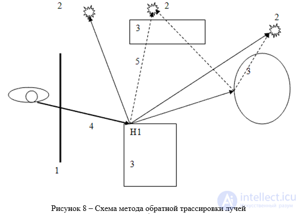
Figure 8 – Diagram of the backward ray tracing method
The algorithm works as follows: from the virtual eye, a ray is emitted through each pixel of the image, and the point where it intersects the surface of the scene is found. Rays emitted from the eye are called primary rays. Suppose the primary ray intersects some object at point H1.
Next, it is necessary to determine, for each light source, whether this point is visible from it. Let us assume for now that all light sources are point sources. Then, for each point light source, a shadow ray is emitted from point H1 toward it. This makes it possible to determine whether the given point is illuminated by a particular source. If the shadow ray intersects other objects located closer than the light source, this means that point H1 lies in shadow from that source and should not be illuminated by it. Otherwise, we compute the illumination according to some local model (Phong, Cook–Torrance, etc.). The illumination from all light sources visible (from point H1) is summed. Next, if the object's material has reflective properties, a reflected ray is emitted from point H1, and the entire tracing procedure is recursively repeated for it. Similar actions must be performed if the material has refractive properties.
Advantages of the ray tracing method:
– the ability to render smooth objects without approximating them with polygonal surfaces (for example, triangles);
– the computational complexity of the method depends only weakly on the complexity of the scene;
– high algorithmic parallelizability of computations — two or more rays can be traced in parallel and independently, screen regions (zones) can be divided for tracing across different cluster nodes, etc;
– culling of invisible surfaces, perspective, and correct changes to the field of view are a logical consequence of the algorithm.
Disadvantages of the method:
A serious drawback of the backward tracing method is performance. The rasterization and scanline method uses data coherence to distribute computations across pixels. Whereas the ray tracing method starts the process of determining a pixel's color anew each time, considering each viewing ray individually. However, this separation also brings certain other advantages, such as the ability to trace more rays than initially intended in order to eliminate jagged edges at specific points in the model. It also governs ray reflection and refraction effects, and, overall, the degree of photorealism of the image.
Bidirectional ray tracing is carried out from two sides: from the camera and from the source. Imagine a scene consisting of a light source and a mirror that reflects all the light onto a plane. Such a scene would potentially be calculated faster using the forward tracing method. Bidirectional tracing (Figure 9) involves emitting rays from the camera and from the source (the maximum tracing depth on each side is fixed). The paths from the camera and from the source then begin to be connected in various ways (the so-called deterministic step of the algorithm). If the connecting rays intersect other objects, the contribution of the entire path will be zero; otherwise, it will be nonzero.
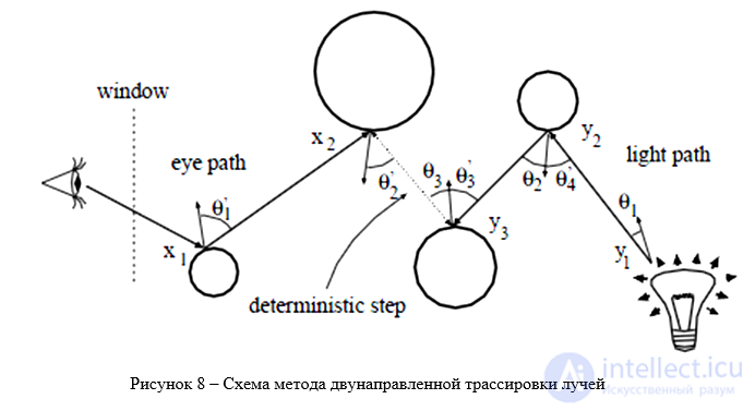
Figure 8 – Diagram of the bidirectional ray tracing method

Comments