
Lecture
Synthesis (from the Greek – combination, placing together) — the process of joining or combining previously separate things or concepts into a whole or a set.
Image synthesis – a field of computer graphics that combines methods for constructing realistic images of the three-dimensional world, including mathematical modeling.
Image synthesis by computer can be represented as a sequence of steps, although in practice these steps are often intertwined within a program:
Objects may be defined as:
– Two-dimensional objects.
They are modeled using primitives such as line segments (defined by two endpoints), polygons (defined by a list of vertices and, possibly, a fill pattern), circles (described by a center, a radius and, possibly, a fill pattern), as well as polynomial curves (defined by their coefficients).
– Three-dimensional objects.
In the three-dimensional case, the corresponding primitives are defined by adding a z coordinate. Primitives that exist only in three-dimensional space can also be introduced: these are polyhedra, pyramids, spheres, cylinders, and surfaces described by certain polynomial functions.
Solid modeling systems generate three-dimensional objects based on:
– interactive specification of parameters (through interaction with the user);
– offline specification
With offline specification, parameters can be entered into data files created by another program, or with the aid of a text editor. Alternatively, a procedural description can be used, similar to that applied for generating fractal curves and landscapes. An object can also be modeled directly as a solid, or indirectly as a volume bounded by a surface.
In systems built on constructive solid geometry, objects are formed from solid primitives, such as blocks, cylinders and spheres.
Primitives can be combined using three-dimensional set-theoretic operations:
– union (joining two objects);
– intersection (extracting the common subset);
– difference (taking the whole of the first object, excluding those parts of it that are common with the second object).
Indirect object definition is carried out in systems with boundary representation. It also makes it possible to perform set-theoretic operations, but here an object is defined as bounded by planar faces, cylindrical faces, or even surface patches given by polynomial functions. This kind of surface description is used by aerospace and automotive companies.
A symmetric object can be described by means of a surface of revolution. A vase or a bottle is defined by its generating curve (a curve describing the silhouette) and an axis of rotation. The sweep operation is analogous to the rotation motion: in this case a volume is formed by moving a face of arbitrary shape, including holes, along a spatial curve.
The shading model must take into account both the properties of the surface (its color, texture, and reflectivity) and the relative position, orientation, and properties of the light sources and other surfaces. Illumination models may account for such light source variants as diffuse light, point sources (the sun or a brightly burning lamp), or distributed sources (a window or a row of fluorescent tubes).
The various materials that scene objects are made of interact with light in different ways. Part of the energy in such an interaction is reflected, part – refracted, and the remaining part – absorbed. There is also a case where the material itself emits light. When a ray of light comes from a light source and strikes the surface of an object, it may be reflected. The reflected ray may then strike the surface of another (or the same) object. A ray that comes directly from the light source is called primary. A ray that has undergone one or more reflections is called secondary. It is possible to build a physical model of light that accounts only for primary illumination (primary rays). In this case the quality of the synthesized images can suffer significantly (Figure 1).
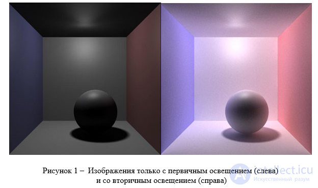
Figure 1 – Images with only primary illumination (left) and with secondary illumination (right)
Another example of simplifying the physical model – forgoing shadow calculation in the scene. Physical models that do not account for the transfer of light between surfaces are called local. Otherwise, the models are called global, or global illumination models.
In 1986, Kajiya formalized the problem that global illumination algorithms must solve. In his work he presented the complete equation of light propagation in a scene. In particular, it was then that the concept of the bidirectional reflectance distribution function (BRDF) emerged. The BRDF is a characteristic of a specific material, showing the fraction of energy reflected from the material as a function of the direction to the light source and to the camera, and the wavelength of light (Figure 2):
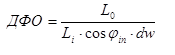 (1)
(1)
where
 – the amount of energy reflected from the material surface in the direction
.  - the amount of energy coming from the source in the direction
, 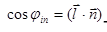 - the cosine of the angle between the normal
  and the vector toward the source.
 - the differential solid angle generated by the direction .
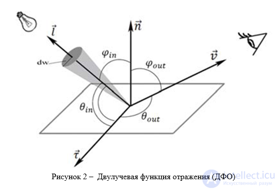
Figure 2 – Bidirectional reflectance distribution function (BRDF)
In the practical implementation of the image synthesis process on a computer, the user faces the task of optimally choosing the resolution, ensuring precise "aiming" at the object, and choosing the focal length. Computational power is used efficiently when the image of the object does not fall outside the frame and occupies the entire frame.
Let us define the observation parameters that ensure the required image quality in terms of discretization. We will assume that the mathematical description of the object's geometry has been performed with sufficient accuracy for the given target task. The task will consist in determining the optimal sampling frequency in a frame-matrix with a fixed number of receptors. It can be solved based on the requirements of the Nyquist criterion: the distance between sampling centers in the image must be at least half the size of the smallest element of the continuous image that is of interest to us. Satisfying the Nyquist criterion, from the consumer's point of view, means that the user will be able to see the small element of the object that they did not want to lose in the given target task. For example, a car designer uses computer graphics to select the exterior appearance. The door handle has the smallest size on the image scale, 3 mm; for this task this is the size of the smallest detail that significantly affects the vehicle's appearance. In accordance with the Nyquist criterion, neighboring pixels in the image must be placed at a distance of 1.5 mm or less. Let us extend the problem statement to the case of the smallest required size on the object itself.
The distance between the sampling centers on the surface of the object and the distance between the receptors are related by the imaging scale. Let us choose the linear resolution L over the surface of the imaged object when modeling at a scale of 1/m. For example, the smallest size of interest for the door handle is L=3 cm; then, when imaging at scale, the distance between the centers of the receptors must be no more than 1.5 mm
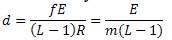
In organizing the image synthesis process, it is important not only to achieve a qualitative (in terms of discretization) image of the object, but also to ensure that the subject of interest falls within the field of view. If the screen has a fixed number of lxl receptors, then it is possible to determine the distance d between the centers of neighboring receptors at which an object of interest with dimensions E will fit entirely within the frame. Let E denote the diameter of the smallest sphere circumscribed around the object, and let us assume that the principal ray is directed at the center of this sphere; then, from simple proportions under central projection, we obtain:
 (2)
(2)
where R is the distance from the projection center to the object (the center of the sphere);
f is the focal length of the observation system; m is the denominator of the image scale.
Using this relationship allows correctly selecting the screen parameters for reliably fitting the object within the frame, provided that the principal ray is directed exactly at the center of the object.
To assess the pictorial quality of an image synthesized on a computer, let us compare the latter, in terms of spectrum, with an ideal image obtained under the same observation conditions for the same scene. An ideal image is one free of noise, blur, and discretization, and free of aberrations, i.e., constructed solely according to the laws of geometric optics. Let us denote such an ideal continuous image by L(x,y), where x,y – are the coordinates in the image field.
In all three-dimensional computer graphics systems, the image synthesis process has two stages: capturing the image by receptors and displaying the content of the receptors as a real image (Figure 3). The structures of the light-receiving part of the screen and of the display device may be entirely different, which must be taken into account when analyzing the spectrum. In physical devices, the receiving part may be a small-format photographic film, while the display medium may be large sheets of photographic paper.
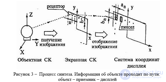
Figure 3 – The synthesis process. Information about the object travels along the path: object – receiver – display
Since it is impossible on a computer to carry out a spatially continuous process of transferring information from every point of the object to the image, image construction, regardless of the method, is performed by sampling information at discrete points. Thus, in ray tracing, information corresponding to the ideal image is transmitted to the receiver plane only at the nodes of the sampling grid. Let us describe this grid mathematically according to the known rules J(x,y)=Comb(x/a)Comb(y/b), where a,b – are the distances between the sampling nodes along the axes of the screen coordinate system, respectively.
Then, on the receiving screen, a discrete image is formed, consisting of a set of regularly arranged point samples, which can be written as L’(x,y)=L(x,y)K(x,y)J(x,y), where K(x,y) – is a dimensionless distortion function caused by the inaccuracy of the mathematical model used to calculate illumination.
Using the convolution operator to describe the propagation of a point sample and the rules of Fourier analysis, we can obtain an expression describing the spectrum of the synthesized raster image:
 (3)
(3)
where
 – the spectrum of the ideal image;
 – the spectrum of the distortion function;
 – the spatial frequencies along the image axes.
Comparing the resulting spectrum with the spectrum of an image in a real matrix receiver continuously viewing the scene, we find that the former differs from the latter only by the omission of the averaging operation over each receptor and the influence of illumination calculation errors. In real devices, within the field of a receptor, energy arrives from many unevenly illuminated points of the object; these sub-energies are averaged into a single sample. The value of that sample is conveyed by a uniform glow across the entire field of the corresponding pixel. In computer graphics, only information about the illumination of a single point of the object reaches the receptor. This sample, when displayed, is spread over the entire pixel field of the image. In some cases, it is proposed to improve display quality by averaging the illumination from the four corner points of the receptor, which leads to a fourfold increase in computation volume and is equivalent to increasing the sampling frequency.
The spectrum of the synthesized image is formed by the repeated repetition of a somewhat distorted spectrum of the image constructed according to the laws of geometric optics. Neighboring spectra partially overlap, as is observed in any discretizing system.
There are two fundamental directions for reducing image synthesis time: eliminating clearly unnecessary computations and parallelizing computations. The need to speed up the synthesis process arises because high-quality and complex images are formed on single-processor machines in tens of minutes, which exceeds even the most modest consumer requirements.

Comments