
Lecture
In 3D computer graphics, normal mapping or Dot3 bump mapping is a texture mapping technique used to simulate the lighting of bumps and dents — an implementation of bump mapping. It is used to add detail without using more polygons. This technique is commonly used to greatly enhance the appearance and detail of a low-polygon model by generating a normal map from a high-polygon model or a height map.
Normal maps are usually stored as ordinary RGB images, where the RGB components correspond to the X, Y, and Z coordinates of the surface normal.
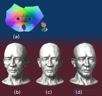
Normal mapping is used to re-detail simplified meshes. The normal map (a) is baked from a model of 78,642 triangles (b) onto a model of 768 triangles (c). This results in the rendering of the 768-triangle model (d).
In 1978, Jim Blinn described how surface normals could be perturbed so that geometrically flat faces would have a detailed appearance. The idea of taking geometric detail from a high-polygon model was introduced in "Fitting Smooth Surfaces to Dense Polygon Meshes" by Krishnamurthy and Levoy, Proc. SIGGRAPH 1996, where this approach was used to create displacement maps over NURBS. In 1998, two papers were presented with key ideas for transferring detail from high-polygon to low-polygon meshes using normal maps: "Appearance Preserving Simplification" by Cohen et al., SIGGRAPH 1998, and "A General Method for Preserving Attribute Values on Simplified Meshes" by Cignoni et al., IEEE Visualization '98. The former introduced the idea of storing surface normals directly in a texture rather than displacements, although this required the low-detail model to be generated by a specific constrained simplification algorithm. The latter presented a simpler approach that separates the high- and low-polygon meshes and allows any attribute of the high-detail model (color, texture coordinates, displacements, etc.) to be recreated in a way that does not depend on how the low-detail model was created. The combination of storing normals in a texture with this more general creation process is still used by most tools available today.
The orientation of the coordinate axes differs depending on the space in which the normal map was encoded. A simple implementation encodes normals in object space so that the red, green, and blue components correspond directly to the X, Y, and Z coordinates. In object space, the coordinate system is constant.
However, object-space normal maps cannot easily be reused across multiple models, since the orientation of the surfaces differs. Because color texture maps can be freely reused, and normal maps generally correspond to a specific texture map, it is desirable for artists that normal maps have the same property.
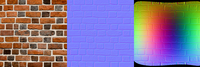
Texture map (left). Corresponding normal map in tangent space (center). Normal map applied to a sphere in object space (right).
Reuse of normal maps became possible through encoding maps in tangent space. Tangent space is a vector space tangent to the surface of the model. The coordinate system changes smoothly (based on the derivatives of position with respect to texture coordinates) across the entire surface.
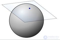
Graphical representation of the tangent space of a single point  on a sphere
Tangent-space normal maps can be identified by their dominant purple color, corresponding to a vector pointing straight out from the surface. .
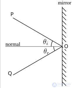
Graphical representation of how the normal vector determines the reflection of a ray.
For each tangent space of a surface in three-dimensional space there are two vectors that are perpendicular to every vector of the tangent space. These vectors are called normal vectors, and the choice between these two vectors gives a description of how the surface is oriented at that point, since the light information depends on the angle of incidence between the ray r and the normal vector n
 , and light will be visible only if
  . In this case the reflection s
 of a ray with direction r along the normal vector nis given by

Intuitively, this simply means that you can only see the outside of an object if you are looking from outside, and only the inside if you are looking from inside. Note that light information is local, and therefore the surface need not be orientable as a whole. This is why, although spaces such as the Mobius strip and the Klein bottle are non-orientable, they can still be rendered.
Normals can be specified using various coordinate systems. In computer graphics it is useful to compute normals relative to the tangent plane of the surface. This is useful because surfaces in applications undergo various transformations, for example during rendering or in skeletal animation, and it is therefore important that the normal vector information be preserved under these transformations. Examples of such transformations are translation, rotation, shear and scaling, perspective projection, or skeletal animation on a finely detailed character.
For the purposes of computer graphics, the most common representation of a surface is triangulation, and as a result the tangent plane at a point can be obtained by interpolating between the planes containing the triangles that intersect that point. Similarly, for parametric surfaces with tangent spaces, the parameterization will give partial derivatives, and these derivatives can be used as the basis of the tangent spaces at each point.
To find the perturbation in the normal, the tangent space must be calculated correctly. Most often the normal is perturbed in the fragment shader after the model and view matrices have been applied. Typically the geometry provides a normal and a tangent. The tangent is part of the tangent plane and can be transformed simply using the linear part of the matrix (the upper 3x3). The normal, however, must be transformed by the inverse transpose. Most applications want the bitangent to correspond to the transformed geometry (and the associated UVs). Therefore, instead of forcing the bitangent to be perpendicular to the tangent, it is generally preferable to transform the bitangent in the same way as the tangent. Let t be the tangent, b be the bitangent, n be the normal, M 3x3 be the linear part of the model matrix, and V 3x3 be the linear part of the view matrix.



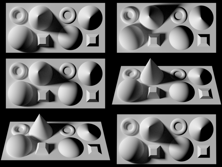
Rendering using the normal mapping technique. On the left are several solid meshes. On the right is a flat surface with a normal map computed from the meshes on the left.
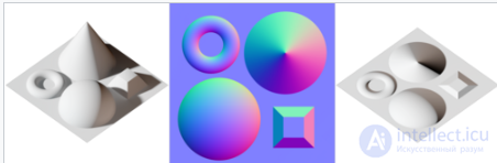
Example of a normal map (center) together with the scene from which it was calculated (left), and the result when applied to a flat surface (right). This map is encoded in tangent space.
To compute the Lambertian (diffuse) lighting of a surface, the unit vector from the shading point to the light source is dotted with the unit normal vector of that surface, and the result is the light intensity at that surface. Imagine a polygonal model of a sphere — you can only approximate the shape of the surface. By using a 3-channel bitmap image textured over the entire model, more detailed normal vector information can be encoded. Each channel in the bitmap corresponds to a spatial dimension (X, Y, and Z). These spatial dimensions relate to a constant coordinate system for object-space normal maps, or to a smoothly varying coordinate system (based on the derivatives of position with respect to texture coordinates) in the case of tangent-space normal maps. This adds much more detail to the surface of the model, especially when combined with advanced lighting techniques.
Unit normal vectors corresponding to the texture coordinates u,v are displayed on normal maps. Only vectors pointing toward the viewer are present (z: from 0 to -1 for a left-handed orientation), since vectors on geometry that point away from the viewer are never displayed. The mapping is as follows:
  X: from -1 to +1: Red: from 0 to 255
  Y: from -1 to +1: Green: from 0 to 255
  Z: from 0 to -1: Blue: from 128 to 255
                  light green light yellow
  dark cyan light blue light red dark
  blue dark magenta
Since the normal will be used in the dot product calculation to compute diffuse lighting, we can see that {0, 0, –1} will be remapped to the values {128, 128, 255}, giving that sky-blue appearance seen in normal maps (the blue (z) coordinate is the perspective (depth) coordinate, with the flat RG-xy coordinates lying on the screen). {0.3, 0.4, –0.866} will be remapped to the values ( ). The sign of the z-coordinate (blue channel) must be flipped in order to map the normal vector of the normal map to the normal vector of the eye (viewpoint or camera) or of the light vector. Since negative z values mean that the vertex is in front of the camera (rather than behind it), this convention ensures that the surface will glow with maximum intensity precisely when the light vector and the light vector coincide.
Interactive rendering of normal maps was initially possible only on PixelFlow, a parallel rendering machine created at the University of North Carolina at Chapel Hill. Later it became possible to perform normal mapping on high-performance SGI workstations using multi-pass rendering and framebuffer operations, or on low-performance PC hardware using various tricks involving paletted textures. However, with the advent of shaders on personal computers and game consoles, normal mapping became widespread in the early 2000s, and among the first games to implement it were Evolva (2000), Giants: Citizen Kabuto and Virtua Fighter 4 (2001). The popularity of normal mapping for real-time rendering is due to its favorable ratio of quality to processing requirements compared with other techniques for producing similar effects. Much of this efficiency became possible through distance-indexed detail scaling, a technique that selectively reduces the detail of a given texture's normal map (cf. mipmapping), meaning that more distant surfaces require a less complex simulation of lighting. Many authoring pipelines use high-resolution models baked into low/medium-resolution in-game models supplemented with normal maps.
Basic normal mapping can be implemented on any hardware that supports paletted textures. The first game console to have dedicated normal-mapping hardware was the Sega Dreamcast. However, Microsoft's Xbox was the first console to make widespread use of this effect in retail games. Of the sixth-generation consoles, only the PlayStation 2's graphics processor lacks built-in support for normal mapping, although it can be simulated using the vector units of the PlayStation 2 hardware. Xbox 360 and PlayStation 3 games rely heavily on normal mapping and were the first generation of game consoles to use parallax mapping. The Nintendo 3DS has been shown to support normal mapping, as demonstrated in Resident Evil: Revelations and Metal Gear Solid 3: Snake Eater.

Comments