
Lecture
An electric dipole — is a system of two electric charges +q and -q, equal in magnitude and opposite in sign.
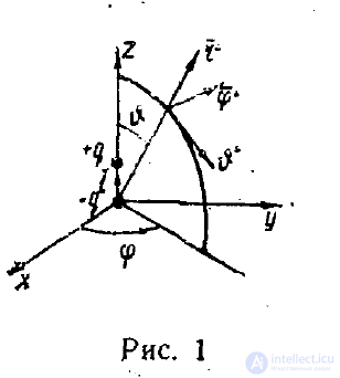
Let us find the field of an electric dipole. For this we introduce a spherical coordinate system 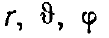 (fig. 1)
(the coordinate <p should not be confused with the potential). According to what was presented in the previous lecture, the potential of this system equals
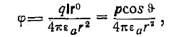
where p = ql — is the electric moment of the dipole.
The field strength equals

Here it is taken into account that, by virtue of axial symmetry, the derivative with respect to the coordinate  equals zero.
As a result we obtain

i.e. the components of the field strength vectors in the spherical coordinate system are equal to
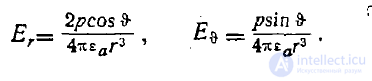
The field lines of the dipole are shown schematically in fig. 2.
A dipole with a dipole moment varying in time is the simplest radiator of radio waves.
Along with the dipole one can imagine more complex neutral systems of charges, called multipoles.
Fig. 3 shows a dipole, a quadrupole and an octupole. Each multipole, like the dipole, has its own moment:
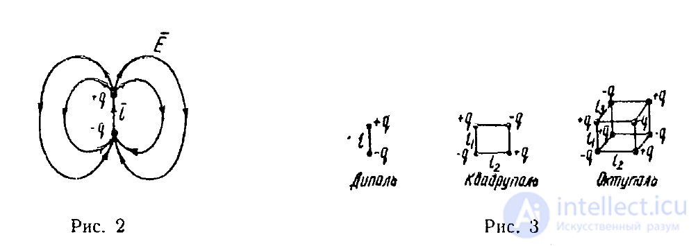
the quadrupole — a quadrupole moment, the octupole — an octupole moment.
There are multipoles of even higher order.
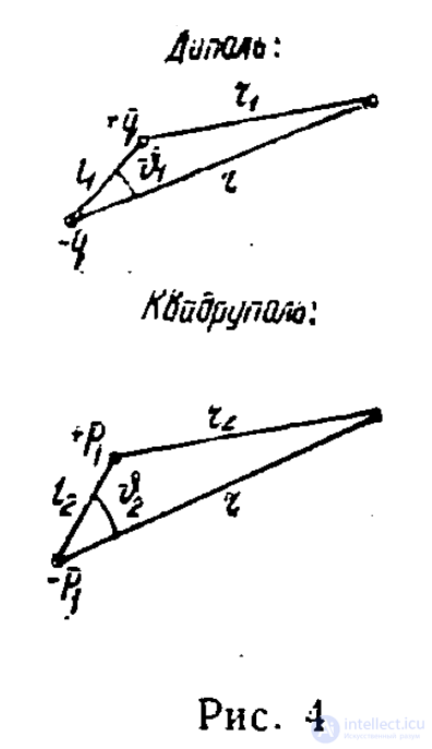
Let us find the potential and moment of a multipole of arbitrary order. The calculations are carried out according to the same scheme by which the moment and potential of a dipole are calculated
(fig. 4) and require no additional explanation
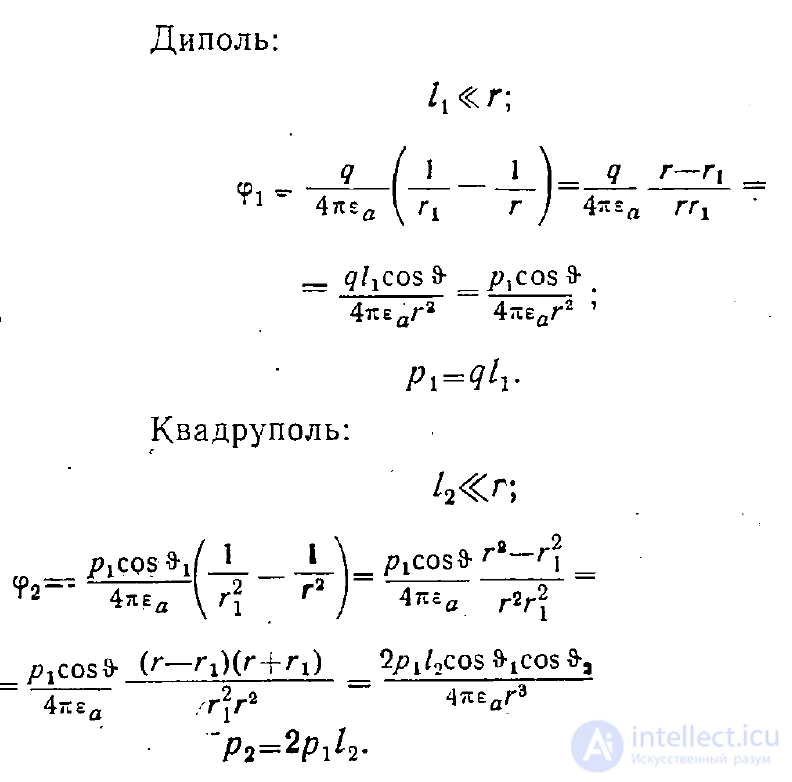
From this, for the potential and moment of a multipole of the l-th order we find
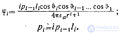
From the formula for the potential it is evident that the field of a multipole decreases very rapidly with distance as its order increases.
A multipole can be regarded as a model of a crystal lattice. Indeed, a crystal, to a first approximation, is imagined as a lattice, at whose nodes positively or negatively charged atomic ions are located.
Faraday was the first to notice that if a dielectric is placed between the plates of a capacitor, an increase in the capacitance of the capacitor occurs, that is, without the dielectric the potential difference was determined by the formula 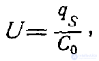
where
qs—the charge on the capacitor plate (fig. 5,a),
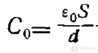 —the capacitance of the capacitor, and for the field strength one obtained

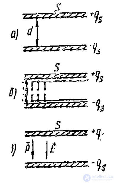
Fig. 5
When a dielectric is introduced, the potential difference decreases due to the increase in capacitance and, consequently, the field strength decreases. This effect can be explained by the fact that under
the influence of the electric field the molecules of the dielectric substance become polarized, and as a result a surface charge of opposite sign to the original
surface charge is formed on the capacitor plates (fig. 5,6). So that now instead of (1) we have
 (2)
(2)
where 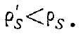
If we introduce the dipole moment per unit volume P, otherwise called the polarization vector, which, as can be seen
from the relation
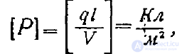
has the dimension of surface charge density, then one can assume that
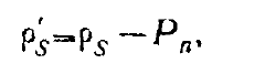
where Pn—is its component normal to the capacitor plate (fig. 5,c).
Then from the formula
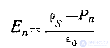
we find that
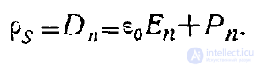
Generalizing, we can write that inside the dielectric
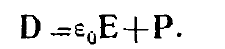 (3)
(3)
Substituting this expression into the third Maxwell equation
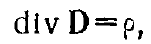
we find

Unlike ρ — the density of free charges — div P is called the density of bound or polarization charges, i.e.

In the case of an isotropic dielectric the vector P is proportional to the vector E, i.e.-
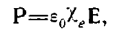 (4)
(4)
where  is called the electric susceptibility.
Correspondingly

i.e. the relative permittivity equals
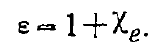 (5)
(5)
Taking this equality into account, instead of (4) we can write
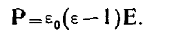 . (6)
. (6)
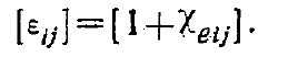
In the case of an anisotropic dielectric the electric susceptibility is a tensor.
According to (5) the components of the permittivity tensor are related to the components of the electric susceptibility tensor by the formula
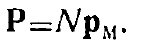
The dipole moment per unit volume equals the product of the dipole moment of a single molecule p_m by the number of molecules N per unit
volume, i.e.
A molecule becomes polarized under the action of a field, and therefore the dipole moment p_m must be proportional to the field strength. However, the question arises as to which field acts on an individual molecule.
After all, we introduced the vector P on the assumption of continuity of the dielectric substance. Under this assumption there are no gaps between molecules. But in reality every molecule is in a vacuum (e = 1), even though it is surrounded by other molecules. Therefore one cannot expect that the field which induces the moment p_m will equal the field E, which is obtained under the assumption of continuity of the dielectric.
We must, therefore, consider that this moment is induced by some effective field E_eff such that
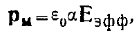
where a — is the so-called polarizability of the molecule, and
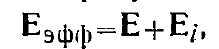
E_1 — is the additional «internal» field, which we need to find.
So, each molecule is located in some cavity inside the dielectric.
The simplest assumption about the shape of the cavity, which suggests itself, is that this cavity is a sphere. Outside this sphere the polarization vector
P acts. This means that on the surface of the sphere there acts a polarization surface charge of density, according to (3), equal to
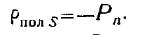
What does the «—» sign mean? In the case Ds=σs the vector D emerges from positive charges. Consequently, the «—» sign means that the vector P emerges from negative charges (fig. 6).
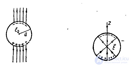
Fig. 6 Fig. 7
The field strength vector E_i, acting on a molecule located at the center of the sphere, is shown in fig. 7. This field strength is created by the polarization surface charge of density

The field dE_i, created by this surface charge, located on an element
