
Lecture
Faraday's law of electromagnetic induction is one of the most important laws of electrodynamics, stating that
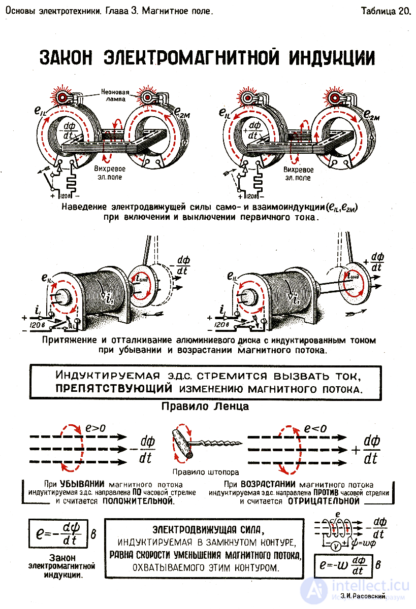
for any closed loop, the electromotive force (EMF) induced in it by a magnetic field equals the rate of change of the magnetic flux through that loop, taken with a minus sign,
or, omitting the details,
the generated EMF is proportional to the rate of change of the magnetic flux.
A loop is understood to be any closed curve in space; it may move and deform.
If a thin wire is laid along such a curve, the EMF will manifest itself as an induced current flowing through it, which can be used technically. This effect underlies the operating principles of transformers, chokes, and many types of electric motors and generators. In this case, the induced current is directed so that its action opposes the cause that produced it (Lenz's rule).
In 1831 Michael Faraday experimentally discovered that at the terminals of an open conducting loop placed in a varying magnetic
field, an electromotive force E arises, whose magnitude is equal to the rate of change of the
magnetic flux crossing this loop:
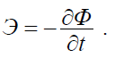 . (2.8)
The EMF induced in the loop L can be represented as the circulation of the electric field intensity vector E
r
around this loop
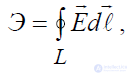
and the magnetic flux can be defined as
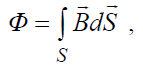
where S is the area of the surface bounded by the loop L. Taking this into account, equality (2.8) can be written as follows:
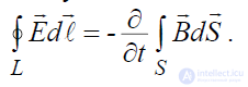 . (2.9)
Applying Stokes' theorem to the left-hand side of the last expression, we arrive at the relation:
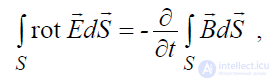
from which the equality follows:
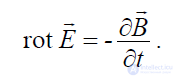 . (2.10)
Expressions (2.9) and (2.10) represent the integral and differential forms of Faraday's law of electromagnetic induction.
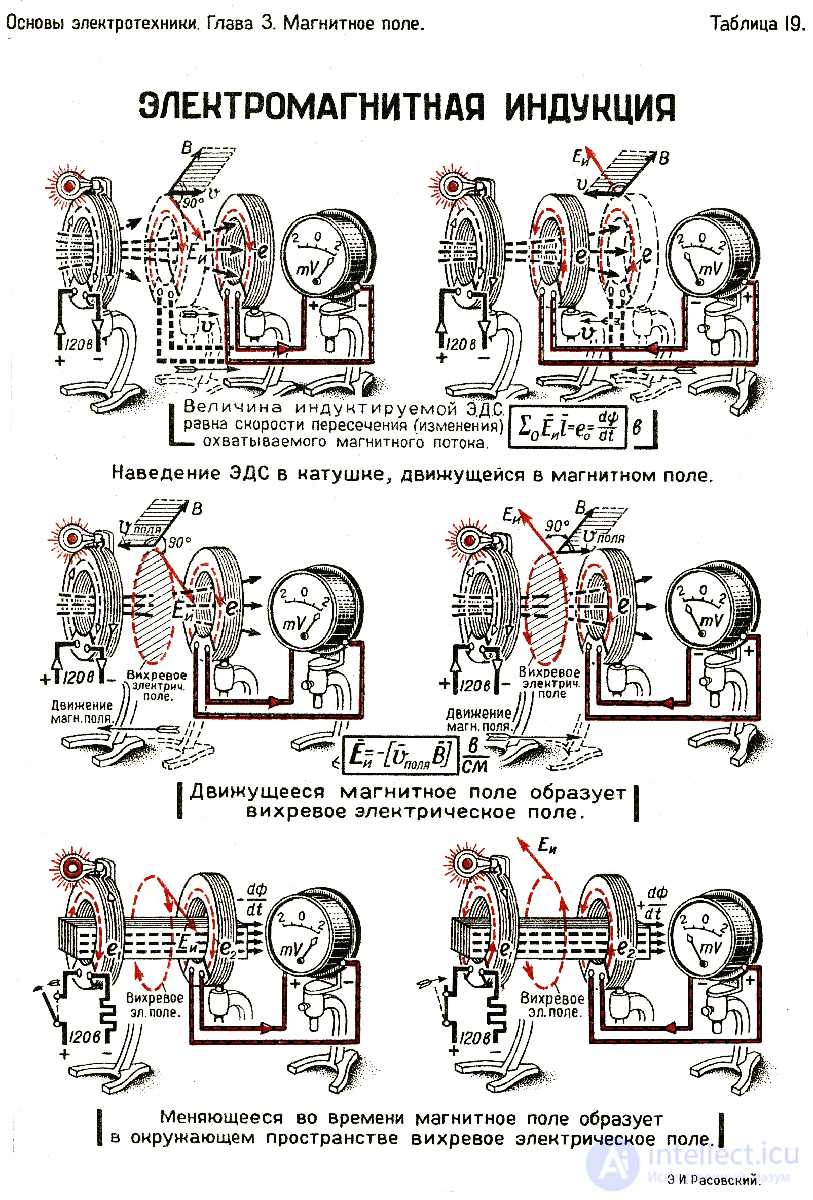
Electromagnetic induction was discovered independently by Michael Faraday and Joseph Henry in 1831, but Faraday was the first to publish the results of his experiments.
In the first experimental demonstration of electromagnetic induction (August 1831), Faraday wound two wires around opposite sides of an iron torus (a design similar to a modern transformer). Based on his assessment of the recently discovered properties of the electromagnet, he expected that when current was switched on in one wire, a wave of some kind would pass through the torus and produce some electrical effect on its opposite side. He connected one wire to a galvanometer and watched it while connecting the other wire to a battery. Indeed, he saw a brief surge of current (which he called a "wave of electricity") when he connected the wire to the battery, and another such surge when he disconnected it. Within two months Faraday found several other manifestations of electromagnetic induction. For example, he saw current surges when he quickly inserted a magnet into a coil and pulled it back out, and he generated a steady current in a copper disk rotating near a magnet with a sliding electrical contact (the "Faraday disk").
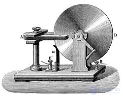
Faraday disk
Faraday explained electromagnetic induction using the concept of so-called lines of force. However, most scientists of the time rejected his theoretical ideas, mainly because they were not formulated mathematically. Maxwell was the exception, using Faraday's ideas as the foundation for his quantitative electromagnetic theory. In Maxwell's works, the time-varying aspect of electromagnetic induction is expressed in the form of differential equations. Oliver Heaviside called this Faraday's law, although it differs somewhat in form from the original version of Faraday's law and does not account for EMF induced by motion. Heaviside's version is the form recognized today as part of the set of equations known as Maxwell's equations.
Emil Khristianovich Lenz formulated the law (Lenz's rule) in 1834, which describes the "flux through the circuit" and gives the direction of the induced EMF and current resulting from electromagnetic induction.
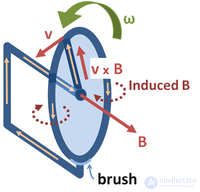
An electric generator based on the Faraday disk. The disk rotates with angular velocity ω , while the conductor, positioned along the radius, moves through a static magnetic field B. The magnetic Lorentz force v×B
 creates a current along the conductor toward the rim, and the circuit is then closed through the lower brush and the disk's support axle. Thus, current is generated as a result of mechanical motion.
The phenomenon of EMF arising, according to Faraday's law of induction, from the relative motion of a loop and a magnetic field underlies the operation of electric generators. If a permanent magnet moves relative to a conductor, or conversely the conductor moves relative to the magnet, an electromotive force arises. If the conductor is connected to an electrical load, a current will flow through it, and consequently the mechanical energy of motion will be converted into electrical energy. One possible implementation of this idea is the Faraday disk, shown in simplified form in the figure on the right.
In the Faraday disk example, the disk rotates in a uniform magnetic field perpendicular to the disk, which results in a current in the radial arm due to the Lorentz force. It is interesting to understand why mechanical work is required to drive this current. When the generated current flows through the conducting rim, by Ampere's law this current creates a magnetic field (labeled "Induced B" in the figure). The rim thus becomes an electromagnet that resists the rotation of the disk (an example of Lenz's rule). On the far side of the figure, the return current flows from the rotating arm through the far side of the rim to the lower brush. The field B produced by this return current opposes the applied field, causing a decrease in flux through the far side of the circuit, counteracting the increase in flux caused by the rotation. On the near side of the figure, the return current flows from the rotating arm through the near side of the rim to the lower brush. The induced field B increases the flux on this side of the circuit, counteracting the decrease in flux caused by the rotation. Thus, both sides of the circuit generate an EMF that opposes the rotation. The energy required to keep the disk moving against this reactive force is exactly equal to the electrical energy produced (plus energy to compensate for losses due to friction, Joule heating, and so on). This behavior is common to all generators that convert mechanical energy into electrical energy.
Although Faraday's law describes the operation of all electric generators, the detailed mechanism can differ from case to case. When a magnet rotates around a stationary conductor, the changing magnetic field creates an electric field, as described by the Maxwell-Faraday equation, and this electric field pushes charges through the conductor. This case is called induced EMF. On the other hand, when the magnet is stationary and the conductor rotates, the moving charges are acted upon by a magnetic force (as described by the Lorentz force law), and this magnetic force pushes charges through the conductor. This case is called motional EMF.
An electric generator can operate "in reverse" and become a motor. Consider, for example, the Faraday disk. Suppose a constant current flows through the conducting radial arm from some voltage source. Then, by the Lorentz force law, this moving charge experiences a force in the magnetic field B, which will rotate the disk in a direction determined by the left-hand rule. In the absence of effects causing dissipative losses, such as friction or Joule heating, the disk will rotate at a rate such that  equals the voltage driving the current.
The EMF predicted by Faraday's law is also the reason electric transformers work. When the electric current in a wire loop changes, the changing current creates a varying magnetic field. A second wire within reach of this magnetic field will experience these changes in the magnetic field as changes in the magnetic flux linked with it . The electromotive force arising in the second loop is called the induced EMF, or transformer EMF. If the two ends of this loop are connected through an electrical load, a current will flow through it.
Faraday's law is used to measure the flow rate of electrically conductive liquids and suspensions. Such instruments are called magnetic flowmeters. The induced voltage ℇ, generated in a magnetic field B due to a conductive liquid moving at velocity v , is determined by the formula:
 ,
,
where ℓ is the distance between the electrodes in the magnetic flowmeter.
A magnetic field has an orienting effect on a current loop. Consequently, the torque experienced by the loop is the result of forces acting on its individual elements. Ampere established that the force dF with which a magnetic field acts on an element dl of a current-carrying conductor located in the magnetic field is equal to
dF =I[dl,B]
Where dl is a vector whose magnitude equals dl and whose direction coincides with the direction of the current, and B is the magnetic induction vector.
The direction of the vector dF can be found by the general rules of the vector product, from which the left-hand rule follows: if the palm of the left hand is positioned so that the vector B enters it, and the four extended fingers point in the direction of the current in the conductor, then the bent thumb will show the direction of the force acting on the current. The magnitude of the Ampere force is calculated by the formula
dF = IB dl sin α
where α is the angle between the vectors dl and B.
Ampere's law is applied to determine the force of interaction between two currents. Consider two infinite straight parallel currents I1 and I2 (the directions of the currents are shown in Fig. 1), with a distance R between them. Each of the conductors creates a magnetic field that acts (by Ampere's law) on the other current-carrying conductor. Let us consider the force with which the magnetic field of current I1 acts on an element dl of the second conductor carrying current I2. The current I1 creates a magnetic field around itself, whose magnetic induction lines are concentric circles. The direction of the vector B1 is determined by the right-hand screw rule, and its magnitude is equal to

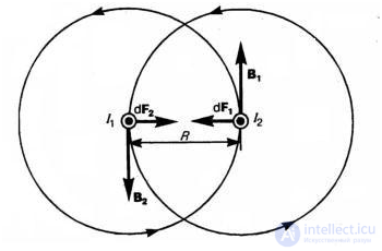
Fig. 1
The direction of the force dF with which the field B acts on the element dl of the second current is determined by the left-hand rule and is shown in Fig. 1. The magnitude of the force, taking into account that the angle α between the elements of current I2 and the vector B1 is a right angle,
dF1 = I2B1dl
substituting the value for B1
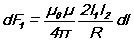
Reasoning similarly, it can be shown that the force dF2 with which the magnetic field of current I2 acts on an element dl of the first conductor carrying current I1 is directed the opposite way and is equal in magnitude to
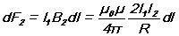
Let us compare these last two expressions. It turns out that
dF1 = dF2,
i.e., two parallel currents in the same direction attract each other with a force
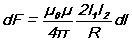
If the currents have opposite directions, then, using the left-hand rule, it can be shown that a repulsive force acts between them.
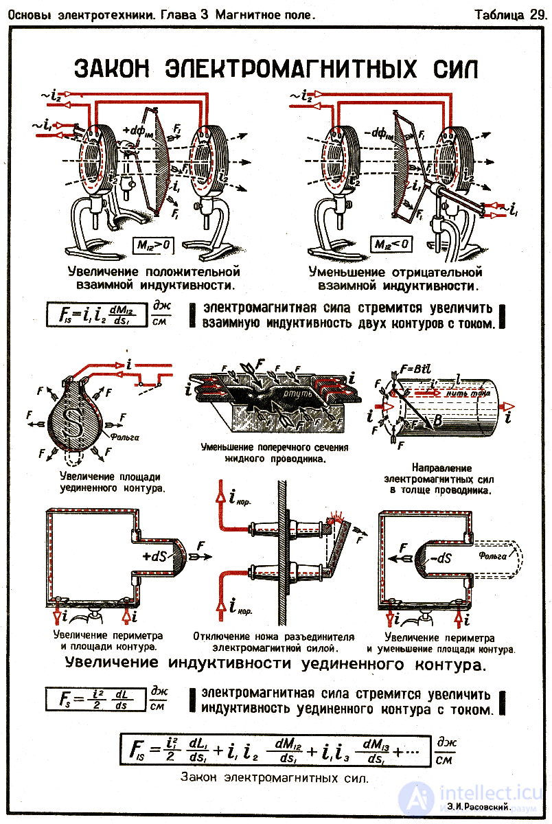
Thus, Ampere's law of electromagnetic forces states: the force of mechanical interaction between a conductor carrying current I and a magnetic field with induction B is directly proportional to the product of the magnetic induction, the length of the conductor, and the current strength in the conductor.
F = B l I sin α

Comments