
Lecture
Polarization – is a characteristic of a harmonic electromagnetic wave that determines the direction of the intensity vector  of its electric field over the period of oscillation.
Wave polarization — a characteristic of transverse waves, describing the behavior of the oscillating quantity's vector in the plane perpendicular to the direction of wave propagation. In flat space it defines the behavior for the vector of the oscillating quantity, which is perpendicular to the direction of wave propagation.
In a longitudinal wave polarization cannot arise, since the direction of oscillation in waves of this type always coincides with the direction of propagation.
For electromagnetic waves, polarization — is the phenomenon of directed oscillation of the electric field intensity vectors  or the magnetic field intensity vectors
  .
.
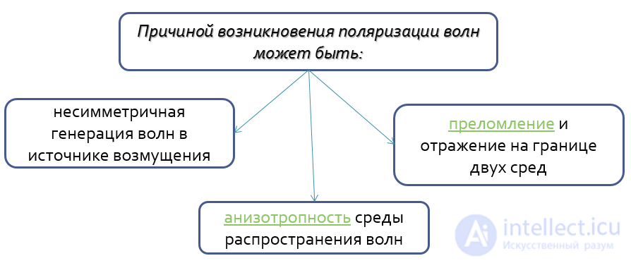
The cause of the emergence of wave polarization
The discovery of polarized light waves was preceded by the work of many scientists. In 1669, the Danish scientist Rasmus Bartholin reported on his experiments with calcite crystals (CaCO3), most often having the shape of a regular rhombohedron, which were brought back by sailors returning from Iceland. He was surprised to discover that a ray of light, upon passing through the crystal, splits into two rays (now called the ordinary and extraordinary rays). Bartholin carried out careful studies of the phenomenon of double refraction he had discovered, but was unable to provide an explanation for it.
Twenty years after E. Bartholin's experiments, his discovery attracted the attention of the Dutch scientist Christiaan Huygens. He himself began studying the properties of Iceland spar crystals and gave an explanation of the phenomenon of double refraction based on his wave theory of light. In doing so he introduced the important concept of the crystal's optical axis, around which rotation produces no anisotropy of the crystal's properties, that is, no dependence on direction (of course, far from all crystals possess such an axis).
In his experiments Huygens went further than Bartholin, passing both rays emerging from the Iceland spar crystal through a second, identical crystal. It turned out that if the optical axes of the two crystals are parallel, no further splitting of these rays occurs. However, if the second rhombohedron is turned 180 degrees about the direction of propagation of the ordinary ray, then upon passing through the second crystal the extraordinary ray undergoes a shift in the direction opposite to the shift in the first crystal, and from such a system both rays emerge joined into a single beam. It was also found that the intensity of the ordinary and extraordinary rays changes depending on the magnitude of the angle between the optical axes of the crystals.
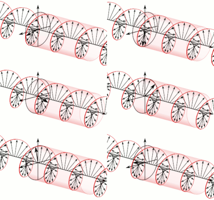
A circularly polarized wave.
These studies brought Huygens right up to the discovery of the phenomenon of light polarization, but he was unable to take the decisive step, since light waves were assumed to be longitudinal in his theory. To explain Huygens's experiments, I. Newton, who adhered to the corpuscular theory of light, put forward the idea of the absence of axial symmetry of a light ray, and thereby took an important step toward understanding the polarization of light.
In 1808, the French physicist Étienne-Louis Malus, while looking through a piece of Iceland spar at the windows of the Luxembourg Palace in Paris glinting in the rays of the setting sun, was surprised to notice that at a certain orientation of the crystal only one image was visible. Based on this and other experiments, and relying on Newton's corpuscular theory of light, he suggested that the corpuscles in sunlight are oriented randomly, but after reflection from some surface or passage through an anisotropic crystal they acquire a definite orientation. He called such "ordered" light polarized.
In 1810, Malus discovered the law expressing the dependence of the intensity of linearly polarized light, after it passes through a polarizer, on the angle between the planes of polarization of the incident light and the polarizer. In the same year he created a quantitative corpuscular theory of light polarization, which explained all polarization phenomena known at the time: double refraction of light in crystals, Malus's law, and polarization upon reflection and refraction. A few years later, Biot discovered the rotation of the plane of polarization, which he himself explained on the basis of Malus's theory.
The phenomenon of polarization was considered proof of the corpuscular theory of light and a refutation of the wave theory. But in 1815 Ampère told Fresnel that polarization could be explained by assuming that the ether undergoes transverse oscillations. In 1817, Young put forward the same hypothesis. In 1821, Fresnel created the wave theory of light polarization.
An electromagnetic wave can be decomposed (both theoretically and practically) into two polarized components, for example polarized vertically and horizontally. Other decompositions are possible, for example along a different pair of mutually perpendicular directions, or into two components having left and right circular polarization. When attempting to decompose a linearly polarized wave into circular polarizations (or vice versa), two components of half intensity will arise.
Both from the quantum and from the classical point of view, polarization can be described by a two-dimensional complex vector (the Jones vector). The polarization of a photon is one of the physical realizations of a qubit.
Sunlight, being thermal radiation, has no polarization, however scattered light from the sky acquires partial linear polarization. The polarization of light also changes upon reflection. These facts underlie the use of polarizing filters in photography (for example, in observations of reflective astronomical bodies, in art photography, aerial photography, or flaw detection), and so on.
Antenna radiation usually has linear polarization.
From the change in the polarization of light upon reflection from a surface, one can judge the structure of the surface, its optical constants, and the sample's thickness.
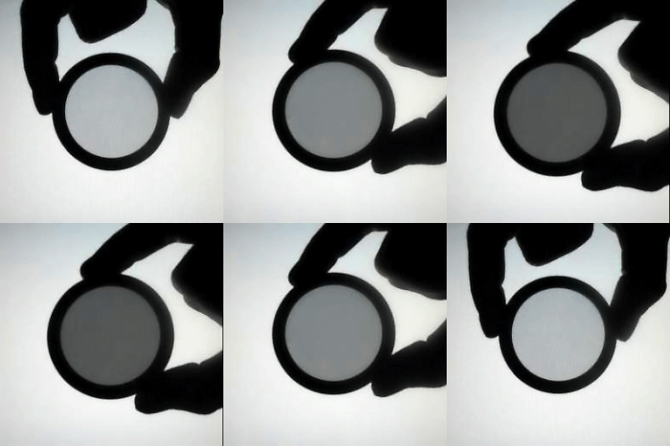
The transmission of polarized light can be limited by simply rotating a polarizing filter
If scattered light is polarized, then, by using a polarizing filter with a different polarization, the transmission of light can be limited. The intensity of light passing through polarizers obeys Malus's law. Liquid crystal displays operate on this principle.
Some living creatures, for example bees, are able to distinguish the linear polarization of light, which gives them additional means of orientation in space. It has been found that some animals, for example the mantis shrimp, are able to distinguish circularly polarized light, that is, light with circular polarization.
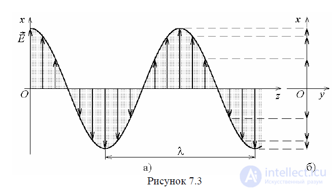
Let us consider an electromagnetic wave (Fig. 7.3, a), for which the change of the vector  over time is described by the expression

Let us fix z = z1 = const , t = var . In the plane z = z1 the hodograph of the vector  is a straight line (Fig. 7.3, b). Such waves are called linearly polarized.
The vector of a linearly polarized wave is not necessarily directed along the x axis; the direction of the line traced by the tip of the vector can be arbitrary: vertical, horizontal, or inclined at any angle to the x, y axes.
Let us consider two waves propagating simultaneously along the z axis:

By the superposition principle, it can be stated that these waves, superimposing on one another, form a resultant wave which will have two components shifted relative to each other by an angle of π / 2. Let us fix the plane z = z1 = const . Let us square the left- and right-hand sides of equations (7.23) and (7.24) and add them.
The resulting equality:
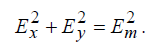 (7.25)
is the equation of a circle.
Thus, over the period of oscillation the tip of the vector  traces out a circle in the plane z = const (Fig. 7.4). An electromagnetic wave possessing this property is called a circularly polarized wave. In space the tip of the vector
  traces out a helical line on the surface of a circular cylinder of radius Em (Fig. 7.5). In the plane const z =, the vector
  can rotate in the left (Fig. 7.4, a) or right (Fig. 7.4, b) direction; accordingly, waves of circular polarization with right-hand and left-hand rotation are distinguished.
Thus, we have shown that a circularly polarized wave is formed by the superposition of two linearly polarized waves, provided three conditions are satisfied:
a) the vectors  of these waves must be directed at an angle of 90° relative to each other;
b) the amplitudes of these waves must be equal;
c) the phase difference between the waves must be ± π/ 2.
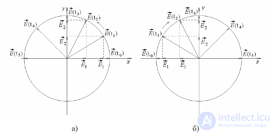
Figure 7.4
It is easy to show that a change of sign in the last condition reverses the direction of rotation of the vector  to the opposite, i.e. a wave with left-hand rotation becomes a right-polarized wave, and conversely, a wave with right-hand rotation becomes left-polarized.
The converse statement also holds true: a linear wave can be represented as the sum of two circularly polarized waves.
Indeed
 , (7.30)
where  are the complex amplitudes of the circularly polarized wave with right-hand and left-hand directions of rotation (Fig. 7.6).
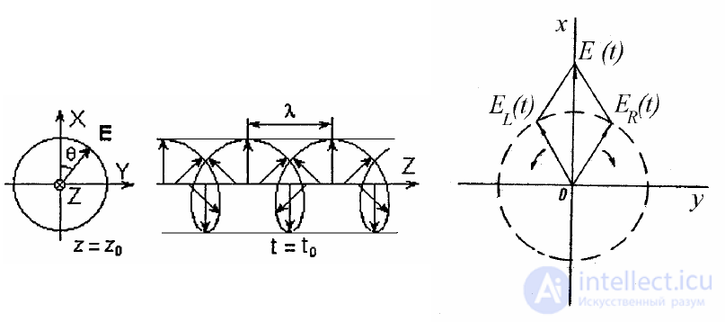
Figure 7.5 Figure 7.6
Earlier we considered•plane electromagnetic waves. These waves are vector waves; they differ from scalar plane waves in that they are characterized not by a single scalar function satisfying the wave equation, but by several such functions. As a result a new factor arises that must be studied, namely polarization.
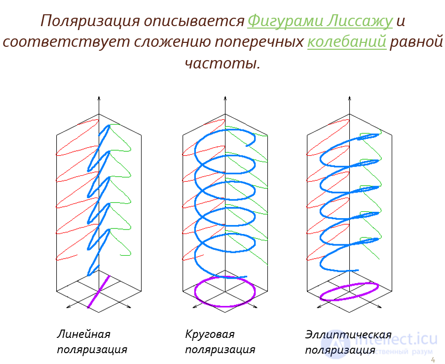
Polarization is described by Lissajous figures, and corresponds to the addition of transverse oscillations of equal frequency (with different phase shifts). When the oscillation frequencies are equal, the Lissajous figures form an ellipse, whose two extreme forms are a circle and a straight line segment.
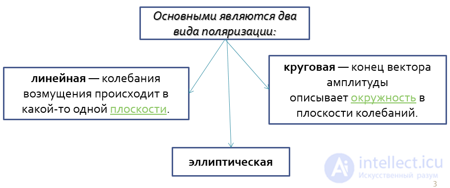
In the general case, for harmonic waves the tip of the oscillating quantity's vector traces an ellipse in the plane transverse to the direction of wave propagation: this is elliptical polarization. Important special cases are linear polarization, in which the oscillations of the disturbance occur in a single plane, in which case one speaks of a "plane-polarized wave", and circular polarization or circular polarization, in which the tip of the amplitude vector traces a circle in the plane of oscillation; circular polarization (like elliptical polarization), depending on the direction of rotation of the vector, can be positive or right-handed and negative or left-handed.
| circular polarization |
elliptical polarization |
linear polarization |

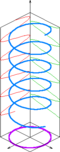 |

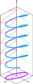 |
 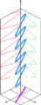 |

Circular polarization on a rubber string, converted into linear polarization
Let us consider the interference in a dielectric of two plane waves whose E vectors are oriented along the ox axis and the oy axis respectively, and let us assume that the amplitudes and initial phases of these waves are different, i.e.
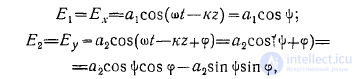
where φ—is the phase difference between the oscillations of these waves. We have
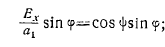

From these two equalities we obtain
 (1)
(1)
or

From this it can be seen that in the plane whose point coordinates are the components of the vector Ex and Ey, over a period of the high frequency  the tip of the vector E traces a second-order curve. In other words, the hodograph of the vector E is a second-order curve
This curve, since it does not extend beyond the bounds of the rectangle with sides 2a1 and 2a2, can only be an ellipse. This ellipse, inscribed in the rectangle with sides 2a1 and 2a2, can have, as
shown in Fig. 1, two positions.
In the figure 0—is the angle between the E y axis and the major axis of the ellipse. The vector H traces the same kind of ellipse over the period T, with the axes of the ellipses of both vectors mutually perpendicular.
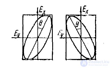
Fig. 1, a, b
Let us first consider two special cases of polarization: linear and circular polarization.
1. Linear polarization. This simplest type of polarization, when the vector E oscillates along a straight line, is obtained when  , where n0 = 0 , 2, 4,... — even numbers, and when
  where n1= 1, 3, 5,... —
-odd numbers.
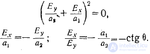
In the first case
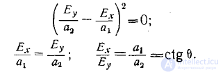
In the second case
The first case is illustrated in Fig. 2, a, and the second in Fig. 2, b.
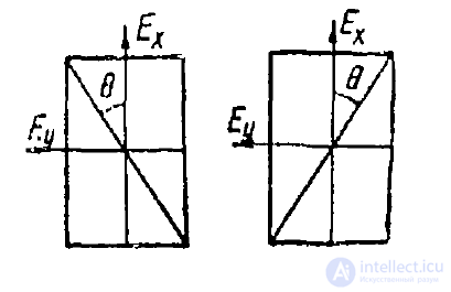
Fig. 2, a, b
This type of polarization is obtained when
a1=a2 = a and
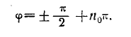
In the first case, when  is taken with a "+" sign,
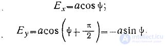
In the second case, when  is taken with a "—" sign,
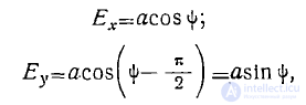
and in both cases
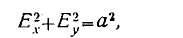
that is, the hodograph of the vector is a circle. ,
Let us determine in which direction the vector E rotates in the first and second cases.
Let us take the derivative with respect to φ of Ex and Ey, and then set ψ = 0. Then in the first case we obtain
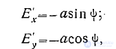
and in the second case
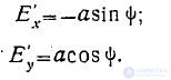
Figure 3 shows the direction of the rotational velocity of the vector E, that is, when before -y- there is a " + " sign , the vector E rotates to the right, or,
in other words, clockwise (Fig. 3a); when before  there is a "—" sign, the vector rotates to the left, or, in other words, counterclockwise (Fig. 3b).
Thus, circular polarization can be of right-hand or left-hand rotation.
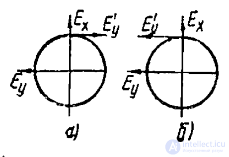
Fig. 3
It is conventionally agreed to consider circular polarization to be right-handed if the observer looks at the approaching wave and sees the vector rotating clockwise. If the observer looks at the approaching wave and sees the vector rotating counterclockwise, then the polarization is left-handed.
Let us first consider the interference of two circularly polarized plane waves, equal in amplitude but of opposite direction of rotation, propagating at the same speed.
It is easy to see that the result is a single linearly polarized wave. Indeed.

Let us consider another case.
Let the interfering waves in question propagate at different speeds
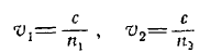
and correspondingly with propagation constants
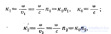
where n1 and n2 — are the refractive indices; 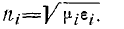
Then, representing the field intensity components of these waves in the form
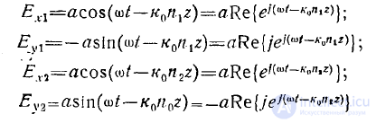
and adding them, we obtain

where the following notation is adopted
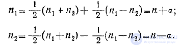
As a result we find
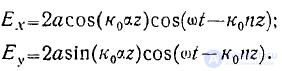
From these expressions it can be seen that the resultant wave has indeed turned out to be linearly polarized, but with a rotating plane of polarization.
Thus, over a path segment of the wave z\—z2, the angle of rotation of the plane of polarization equals

Such rotation of the plane of polarization can occur in ferrites and in the ionosphere. The effect of rotation of the plane of polarization of optical waves was first discovered by Faraday.
From the linear and circular polarizations considered, conclusions about the general case of elliptical polarization can be drawn, illustrated clearly in Fig. 4.
However, a more complete quantitative picture of the nature of polarization in the general case is given by the Stokes parameters and the Poincaré sphere.
The Stokes parameters are the following expressions:
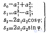 ' (2)
' (2)
It is easy to verify that the following equality holds for these parameters:
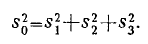
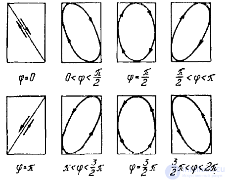
Fig. 4
As a result of purely geometric calculations, the following relations can be obtained:
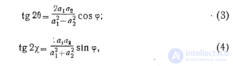
where
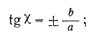
a — is the major, b — is the minor, semi-axis of the polarization ellipse.
Since always a > 0 and b>0, the sign before the ratio according to (4) must be the same as that obtained for sinφ, that is, this sign is determined by the angle φ.
After a series of derivations, the following equalities can be obtained:
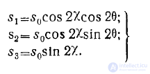 (5)
(5)
These equalities have the following geometric meaning.
The Stokes parameters  can be regarded as rectangular, while the Stokes parameter s0 and the angles 2χ and 2θ can be regarded as the spherical coordinates of a point on the surface of a sphere of radius s0 (Fig. 5).
Unlike the usual spherical coordinate system, here the angle 2χ is measured not from the polar axis 0z, but from the equatorial plane xoy, i.e. the angle 2χ corresponds to geographic latitude.
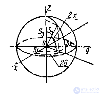
Fig. 5
Every point on the sphere has a clear physical meaning — its coordinates represent all the parameters characterizing the polarization at a fixed wave intensity

The equatorial plane xoy divides polarization into two types.
Above this plane χ > 0 , since s3>0, which according to (2) corresponds to sinφ> 0 .
In this case right-hand rotation polarization is obtained. Below this plane χ<0, since s3<0, and according to (2) this corresponds to sinφ <0. This is left-hand rotation polarization.
Points on the equator where χ = 0, since s3 = 0, which according to (2) corresponds to φ = 0, determine linear polarization.
Points at the poles 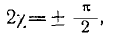 since s1=s2 = 0, which according to (2) corresponds to a1 = a2 and
  determine circular polarization,
with the "north" pole corresponding to right-hand rotation polarization, and the "south" pole to left-hand rotation polarization.
The sphere described here is called the Poincaré sphere.
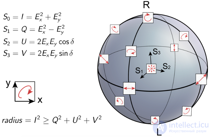
Representation of polarization on the Poincaré sphere via the Stokes parameters
Let us assign to each point of the sphere a small oriented circle lying on the sphere, centered at that point. A parallel projection of such a sphere onto a plane will transform the circles into all possible polarization ellipses. However, each such ellipse occurs twice (corresponding to identical oscillations of the intensity vector, but in antiphase). The Poincaré sphere can be obtained by gluing together pairs of points of the principal meridian that lie on the same parallel.
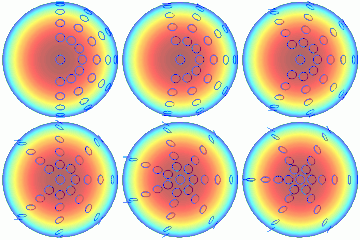


Gluing together points corresponding to identical polarization. Only the upper hemisphere, corresponding to left-hand polarizations, is shown. The azimuthal angle is doubled. The tangent of the elevation angle is also doubled.
A representation of polarized light by means of a single complex number is obtained by stereographic projection of the Poincaré sphere onto the complex plane.

The left-hand image was taken without a filter, the right-hand one — through a polarizing filter
The propagation speed of a wave can depend on its polarization.
Two waves linearly polarized at right angles to each other do not interfere.
Most often this phenomenon is used to create various optical effects, as well as in 3D cinema (IMAX technology), where polarization is used to separate the images intended for the right and left eye.
Circular polarization is used in antennas of space communication links, since for signal reception the orientation of the plane of polarization of the transmitting and receiving antennas is not important. That is, rotation of the spacecraft will not affect the ability to communicate with it. The direction of rotation of the circular polarization of the spacecraft's transceiver antenna must match the direction of rotation of the ground transceiver antenna working with it. The same applies to linearly polarized antennas. In space communications, polarization isolation is used, that is, antennas of opposite directions of polarization rotation, or orthogonal antennas with linear polarization, operate on the same frequency.
A circularly polarized antenna is more difficult to build than a linearly polarized antenna, requiring a polarizer for this purpose. An antenna with right-hand rotation polarization can easily be converted to left-hand rotation. To do this, its polarizer must be rotated 90 degrees relative to the axis of rotation. In general, circular polarization is a theoretical concept. In practice, one speaks of elliptically polarized antennas — with left-hand or right-hand direction of rotation.
Circular polarization of light is also used in the RealD and MasterImage stereo cinema technologies. These technologies are similar to IMAX, with the difference that circular polarization instead of linear polarization makes it possible to preserve the stereo effect and avoid double images with small sideways tilts of the head.
Wave polarization finds application in polarization holography.
Some optical measurement methods are based on polarization. In many other optical methods, polarization is of crucial importance or, at the very least, must be taken into account and controlled; there are too many such examples to list.

Stress in plastic cups
In engineering, the phenomenon of stress-induced birefringence makes it easy to observe stresses in transparent materials. As noted above and shown in the accompanying photograph, the chromaticity of birefringence usually creates colored patterns when observed between two polarizers. When external forces are applied, internal stress induced in the material is observed. In addition, birefringence is often observed due to stresses "frozen" in during manufacturing. This is clearly visible in cellophane tape, whose birefringence is caused by the stretching of the material during manufacturing.
Ellipsometry — is a powerful method for measuring the optical properties of a homogeneous surface. It involves measuring the state of polarization of light after specular reflection from such a surface. This is usually done as a function of the angle of incidence or wavelength (or both). Since ellipsometry is based on reflection, it is not required that the sample be transparent to light or that its back side be accessible.
Ellipsometry can be used to model the (complex) refractive index of a bulk material's surface. It is also very useful for determining the parameters of one or more thin-film layers deposited on a substrate. Because of its reflective properties, not only is the magnitude of the p- and s- polarization components predicted, but also their relative phase shifts upon reflection, compared with measurements made using an ellipsometer. A typical ellipsometer does not measure the actual reflectance (which would require careful photometric calibration of the illuminating beam), but rather the ratio of the p- and s- reflections, as well as the change in the ellipticity of polarization (hence the name) caused by reflection from the surface under study. In addition to its use in science and research, ellipsometers are used in situ, for example to monitor manufacturing processes.

Photomicrograph of grains of volcanic sand; the upper image — plane-polarized light, the lower image — cross-polarized light, the scale bar at lower left is 0.25 millimeters.
The property of (linear) birefringence is widespread in crystalline minerals and, indeed, was crucial in the original discovery of polarization. In mineralogy this property is often used, employing polarizing microscopes, for the identification of minerals. See the "Optical mineralogy" section for more detail.
Sound waves in solid materials exhibit polarization. The differential propagation of the three polarizations through the earth is of crucial importance in the field of seismology. Horizontally and vertically polarized seismic waves (shear waves) are called SH and SV, while waves with longitudinal polarization (compression waves) are called P-waves.
Similarly, polarizing microscopes can be used to detect foreign bodies in slices of biological tissue if they exhibit birefringence; the (absence or presence of) "polarizing foreign bodies" is often mentioned during autopsy.
We have seen (above) that the type of birefringence of a crystal is useful for its identification, and thus the detection of linear birefringence is especially useful in geology and mineralogy. Linearly polarized light typically has its state of polarization altered when passing through such a crystal, which makes it stand out when viewed between two crossed polarizers, as shown in the photograph above. Similarly, in chemistry the rotation of the polarization axes in a liquid solution can be a useful measurement. In a liquid, linear birefringence is not possible, but circular birefringence can occur when a chiral molecule is present in the solution. When the right- and left-handed enantiomers of such a molecule are present in equal amounts (a so-called racemic mixture), their effects cancel out. However, when only one (or a predominance of one) is present, as is most often the case for organic molecules, a net circular birefringence (or optical activity) is observed, indicating the magnitude of this imbalance (or the concentration of the molecule itself, when it can be assumed that only one enantiomer is present). This is measured using a polarimeter, in which polarized light is passed through a tube containing the liquid, at the end of which is another polarizer that is rotated to reduce the transmission of light through it to zero. [ 23 ] : 360–365 [ 30 ]
In many areas of astronomy, the study of polarized electromagnetic radiation from outer space is of great importance. Although polarization is usually not a factor in the thermal radiation of stars, it is also present in the radiation of coherent astronomical sources (for example, hydroxyl or methanol masers) and incoherent sources, such as large radio lobes in active galaxies and pulsar radio emission (which is sometimes thought to possibly be coherent), and it is also imposed on starlight through scattering by interstellar dust. Besides providing information about the sources of radiation and scattering, polarization also probes the interstellar magnetic field by means of Faraday rotation. The polarization of the cosmic microwave background is used to study the physics of the very early Universe. Synchrotron radiation is inherently polarized. It has been suggested that astronomical sources caused the chirality of biological molecules on Earth, but chiral selection on inorganic crystals has been proposed as an alternative theory.

The effect of a polarizer on reflections from muddy water. In the picture on the left, a horizontally oriented polarizer predominantly transmits these reflections; rotating the polarizer by 90° (right), as if looking through polarized sunglasses, blocks almost all specularly reflected sunlight.
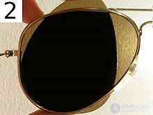
One can check whether sunglasses are polarized by looking through two pairs, one perpendicular to the other. If both are polarized, all light will be blocked.
Unpolarized light, upon reflecting from a specular (glossy) surface, usually acquires some degree of polarization. This phenomenon was observed in the early 1800s by the mathematician Étienne-Louis Malus, after whom Malus's law is named. Polarized sunglasses use this effect to reduce glare from reflections off horizontal surfaces, in particular from the road ahead, seen at a grazing angle.
Owners of polarized sunglasses will sometimes observe unintended polarization effects, such as color-dependent birefringence effects, for example in tempered glass (such as a car window) or objects made of clear plastic, combined with natural polarization by reflection or scattering. Polarized light from LCD monitors (see below) is extremely noticeable when the glasses are worn.
The effect of a polarizing filter (right-hand image) on the sky in a photograph
Polarization is observed in the light of the sky, since it arises from sunlight scattered by aerosols as it passes through Earth's atmosphere. Scattered light produces the brightness and color of a clear sky. This partial polarization of scattered light can be used to darken the sky in photographs, increasing contrast. This effect is most strongly observed at points in the sky forming a 90° angle to the Sun. Polarizing filters make use of these effects to optimize the results when photographing scenes in which reflection or scattering by the sky is present.
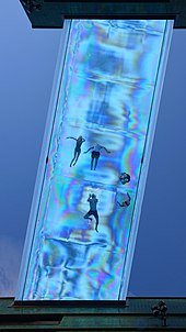
Colored bands in the Sky Pool at Embassy Gardens, observed through a polarizer, caused by birefringence induced by stress in the skylight.
Sky polarization has been used for orientation in navigation. The Pfund sky compass was used in the 1950s for navigation near Earth's magnetic poles, when neither the sun nor the stars were visible (for example, under daytime cloud cover or at twilight). It has been controversially suggested that the Vikings used a similar device (the "sunstone") on their extensive expeditions across the North Atlantic in the 9th–11th centuries, before the arrival of the magnetic compass from Asia in Europe in the 12th century. Related to the sky compass is the "polar clock," invented by Charles Wheatstone at the end of the 19th century.
The principle of liquid crystal display (LCD) technology is based on the rotation of the linear polarization axis by the liquid crystal matrix. Light from the backlight (or the rear reflective layer in devices that do not include or require a backlight) first passes through a linear polarizing sheet. This polarized light passes through the actual liquid crystal layer, which may be organized into pixels (for a television or computer monitor) or in another format, such as a seven-segment display or a display with custom characters for a specific product. The liquid crystal layer is formed with consistent right-handed (or left-handed) chirality, essentially consisting of tiny helices. This causes circular birefringence and is designed so that a 90-degree rotation of the state of linear polarization takes place. However, when voltage is applied to the cell, the molecules straighten out, reducing or completely eliminating the circular birefringence. On the visible side of the display is another linear polarizing sheet, usually oriented at 90 degrees to the one behind the active layer. Therefore, when circular birefringence is eliminated by applying sufficient voltage, the polarization of the transmitted light remains at a right angle to the front polarizer, and the pixel appears dark. However, in the absence of voltage, the 90-degree rotation of polarization causes it to align exactly with the axis of the front polarizer, allowing light to pass through. Intermediate voltages produce an intermediate rotation of the polarization axis, and the pixel has an intermediate intensity. Displays based on this principle are widespread and are now used in the overwhelming majority of televisions, computer monitors, and video projectors, making the previous CRT technology essentially obsolete. The use of polarization in the operation of LCDs immediately becomes apparent to a person wearing polarized sunglasses, which often makes the display unreadable.
In an entirely different sense, polarization encoding has become the leading (though not the only) method of transmitting separate images for the left and right eyes on stereoscopic displays used for 3D films. This involves separate images intended for each eye, either projected from two different projectors with orthogonally oriented polarizing filters, or, more typically, from a single projector with time-multiplexed polarization (a device that rapidly alternates polarization for successive frames). Polarized 3D glasses with matching polarizing filters ensure that each eye receives only the intended image. Historically, such systems used linear polarization encoding, since it was inexpensive and provided good separation. However, circular polarization makes the separation of the two images insensitive to head tilt and is widely used in today's 3D film screenings, for example the system from RealD. Projecting such images requires screens that preserve the polarization of the projected light when viewed in reflection (for example, silver screens); an ordinary diffuse white projection screen causes depolarization of the projected images, making it unsuitable for this application.
Although CRT displays are now obsolete, they suffered from reflection off the glass envelope, which caused glare from room lighting and, consequently, poor contrast. Several anti-glare solutions were used to address this problem. One solution used the principle of reflection of circularly polarized light. A circular polarizing filter in front of the screen allows only (say) right circularly polarized room light to pass through. Now, right circularly polarized light (depending on the convention used) has the direction of its electric (and magnetic) field rotating clockwise as it propagates in the +z direction. Upon reflection, the field still has the same direction of rotation, but now the propagation is in the −z direction, making the reflected wave left circularly polarized. When a right circular polarizing filter is placed in front of the reflective glass, the unwanted light reflected from the glass will therefore be in exactly the polarization state that is blocked by this filter, eliminating the reflection problem. The change in circular polarization upon reflection, and the resulting elimination of reflections, can easily be observed by looking in a mirror while wearing 3D glasses that use left and right circular polarization in the two lenses. Closing one eye, the other eye will see a reflection in which it cannot see itself; this lens appears black. However, the other lens (over the closed eye) will have the correct circular polarization, allowing the open eye to easily see the closed eye.
All radio antennas (and microwave antennas) used for transmission or reception are inherently polarized. They transmit signals with a particular polarization (or receive them), while being completely insensitive to the opposite polarization; in some cases this polarization is a function of direction. Most antennas are nominally linearly polarized, but elliptical and circular polarization are also possible. In the case of linear polarization, the same type of filtering described above is possible. In the case of elliptical polarization (circular polarization is actually just a special case of elliptical polarization, where the lengths of both axes are equal), filtering out a single angle (for example, 90°) will have practically no effect, since the wave at any given moment can be at any of the 360 degrees.
The overwhelming majority of antennas are linearly polarized. In fact, it can be shown from symmetry considerations that an antenna lying entirely within a plane that also includes the observer can have polarization only in the direction of that plane. This applies to many cases, making it easy to deduce the polarization of such an antenna in the intended direction of propagation. Thus, a typical rooftop Yagi antenna or log-periodic antenna with horizontal conductors, viewed from a second station in the direction of the horizon, is necessarily horizontally polarized. But a vertical "whip antenna" or an AM broadcast tower used as an antenna element (again, for observers horizontally offset from it) will transmit with vertical polarization. A turnstile antenna, with its four arms in a horizontal plane, also transmits horizontally polarized radiation in the direction of the horizon. However, when the same turnstile antenna is used in "axial mode" (upward, for the same horizontally oriented structure), its radiation has circular polarization. At intermediate elevations it has elliptical polarization.
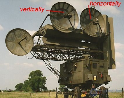
Figure 1. The missile guidance station radar of the S-75 surface-to-air missile system ("Fan Song E").
Polarization is important in radio communications because, for example, if one tries to use a horizontally polarized antenna to receive a vertically polarized transmission, the signal strength will be substantially reduced (or, under very controlled conditions, reduced to zero). This principle is used in satellite television to double the channel capacity in a fixed frequency band. The same frequency channel can be used for two signals broadcast in opposite polarizations. By tuning the receiving antenna to one polarization or the other, either signal can be selected without interference from the other.
Particularly because of the presence of the ground, there are some differences in propagation (as well as in the reflections responsible for television ghosting) between horizontal and vertical polarization. AM and FM broadcast radio stations usually use vertical polarization, while television uses horizontal polarization. At low frequencies, especially, horizontal polarization is avoided. This is because the phase of a horizontally polarized wave is reversed upon reflection from the ground. A distant station in the horizontal direction will receive both the direct and the reflected wave, which thus tend to cancel each other out. This problem is avoided by using vertical polarization. Polarization is also important when transmitting radar pulses and receiving radar reflections with the same or a different antenna. For example, backscatter of radar pulses from raindrops can be avoided by using circular polarization. Just as the specular reflection of circularly polarized light reverses the handedness of the polarization, as discussed above, the same principle applies to scattering by objects much smaller than the wavelength, such as raindrops. On the other hand, reflection of this wave from an irregular metallic object (such as an aircraft) usually results in a change of polarization and (partial) reception of the reflected wave by the same antenna.
The effect of free electrons in the ionosphere, combined with Earth's magnetic field, causes Faraday rotation, a kind of circular birefringence. This is the same mechanism that can rotate the axis of linear polarization by electrons in interstellar space, as mentioned below. The amount of Faraday rotation caused by such a plasma is significantly exaggerated at lower frequencies, so at the higher microwave frequencies used by satellites the effect is minimal. However, medium- or short-wave transmissions received after refraction by the ionosphere are strongly affected. Since the path of the wave through the ionosphere and the vector of Earth's magnetic field along such a path are rather unpredictable, a wave transmitted with vertical (or horizontal) polarization will generally have a resulting polarization at an arbitrary orientation at the receiver.

Circular polarization through a plastic airplane window, 1989.
Many animals are able to perceive some components of light polarization, for example linear horizontally polarized light. This is commonly used for navigational purposes, since the linear polarization of skylight is always perpendicular to the direction of the sun. This ability is very widespread among insects, including bees, which use this information to orient their communication dances. Sensitivity to polarization has also been observed in species of octopus, squid, cuttlefish, and mantis shrimp. In the latter case, one species measures all six orthogonal polarization components and is believed to have optimal polarization vision. The rapidly changing, brightly colored skin patterns of cuttlefish, used for communication, also include polarization patterns, and mantis shrimp are known to have polarization-selective reflective tissue. Pigeons were thought to perceive the polarization of the sky and to use it as one of the means of assistance in homing, but research indicates that this is a popular myth.
The unaided human eye is weakly sensitive to polarization, without the need for auxiliary filters. Polarized light produces a very faint pattern near the center of the field of view, called Haidinger's brush. This pattern is very difficult to see, but with practice one can learn to detect polarized light with the naked eye.
It is well known that electromagnetic radiation carries a definite linear momentum in the direction of propagation. In addition, however, light carries a definite angular momentum if it has circular polarization (or partially so). Compared with lower frequencies, such as microwaves, the magnitude of the angular momentum in light, even purely circularly polarized light, compared with the linear momentum of the same wave (or radiation pressure), is very small and difficult even to measure. Nevertheless, it has been used in an experiment to achieve speeds of up to 600 million revolutions per minute

Comments