
Lecture
Here we give the energy definition of the reflection and transmission coefficients.
The reflection coefficient is defined as the ratio of the normal component of the energy flux density of the reflected wave from a unit of the interface surface to the normal component
of the energy flux density of the incident wave on the same unit of surface (fig. 1), i.e.,
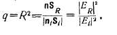 (1)
(1)
where  are the Poynting vectors.
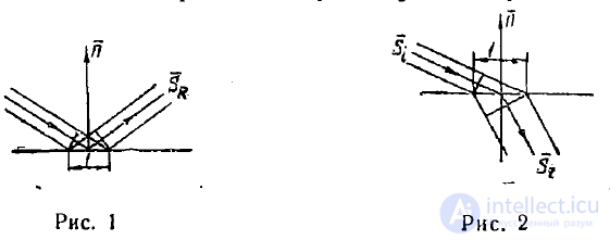
The transmission coefficient is defined analogously, that is, it is the ratio of the normal component of the energy flux density of the transmitted wave through a unit of the interface surface to the normal component of the energy flux density of the incident wave on the same unit of surface (fig. 2);
at  it equals
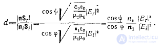 (2)
(2)
Substituting formulas (8) and (11) from lecture 16 into (1), we find
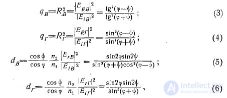
moreover, as is easy to verify, the following equalities hold
 (7)
(7)
By virtue of equalities (7) it is sufficient to analyze the reflection coefficients. We will be interested in how these coefficients change with a change of the angle 
First of all, it is obvious that at normal incidence of a wave on the interface there should be no difference between vertical and horizontal polarizations. Indeed, at small angles of incidence  , as follows from Snell's law,

and both formulas (3) and (4) give the same result
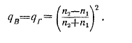
At  in both cases of polarization the reflection coefficients equal 1.
At other angles of incidence, the reflection coefficients for vertical and horizontal polarization can differ significantly from each other.
For horizontal polarization, the reflection coefficient does not become zero at any angle tp.
For vertical polarization, the reflection coefficient becomes zero when

that is, when

Since under this condition
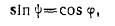
from Snell's law

we find
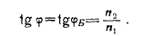 (8)
(8)
The angle  defined by this equality is called Brewster's angle or the angle of total polarization.
A vertically polarized wave incident at Brewster's angle on the interface between two media is not reflected at all, but passes completely into the second medium. This effect is analogous to the phenomenon of matching two long lines with different characteristic impedances.
At any other polarization, at Brewster's angle only the horizontally polarized component of the wave is reflected. That is why Brewster's angle is called the angle of total polarization.
In optics, the effect of total polarization is used to obtain polarized light. Note that when a plane wave is incident on the interface between isotropic and anisotropic media, birefringence occurs. Thus, a plane wave in a crystal splits into two waves. Each of these split waves propagates with its own phase and ray velocities.
Let a wave pass from medium 1 into medium 2, whose refractive index is smaller than the refractive index of medium 1.
Then, according to Snell's law,  has the meaning of the angle of refraction only at angles of incidence <p, satisfying the condition
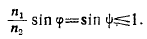 . (9)
. (9)
A question arises: what happens at the interface between the media if this inequality is not satisfied? To answer this question, let us consider the phase factor of the plane wave

Replacing r here, in accordance with fig. 3, with the expression

this phase factor can be represented in the form
 (10)
(10)
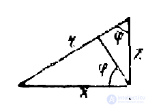
Fig. 3
In the same way one can represent (omitting  ) the phase factor of the wave in medium 2 as well
 (11)
(11)
As follows from Snell's law
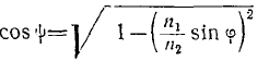
and at angles  not satisfying inequality (9),
 (12)
(12)
—• is a purely imaginary quantity.
The «—» sign is chosen to ensure attenuation of the wave at large distances from the interface. Thus, the phase factor of the wave in medium 2, when (9) is not satisfied, has the form (omitting  )
)
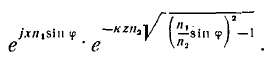 (13)
(13)
Consequently, in the case under consideration there will be no propagation of the wave into the depth of medium 2. The wave process will occur only parallel to the interface, decaying exponentially as the distance z from the interface between the media increases. The reflection coefficients here, in both cases of polarization, as is most easily established from formula (10) of lecture 16, equal unity.
Indeed, the ratio  - in both cases of polarization has the form
  and, consequently,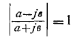
This is why the phenomenon under consideration is called total internal reflection.
The phenomena of reflection and refraction of plane waves at the interface between a dielectric and a metal also occur in accordance with Snell's law, but in this case the refractive index of the second medium, the conductor, is complex.
Therefore the phase factor (11) will take the form

To simplify the calculations, we will assume that the wave is incident on the conductor normally, and then the phase factor of the wave transmitted into the conductor (omitting the factor  ) will equal
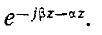
As was shown in lecture 13, in a conductor
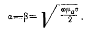 (14)
(14)
The current density created by the field of the wave transmitted into the conductor will equal
 (15)
(15)
From formula (14) it is evident that the higher the frequency  the larger α is and, consequently, the smaller the reciprocal quantity

The quantity  —is called the penetration depth, since, as can be seen from (15), high-frequency currents are practically concentrated in a layer of thickness δ. Numerically, δ equals the distance over
which the field amplitude decreases by a factor of e. At very high radio frequencies, and even more so in the optical range, the value of is very small.
The phenomenon of field concentration in a very thin layer of a conductor is called the skin effect. To characterize the skin effect, in addition to , the concept of surface resistance is also introduced
Zs. To determine it, let us calculate the current flowing through a conductor of thickness d, per strip of width 1 m (fig. 4):

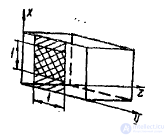
Fig. 4
From this it follows that
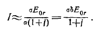
By definition,

where
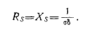
Thus, the surface resistance Zs — is the resistance of a strip of the conductor per unit area (double hatching in fig. 4).
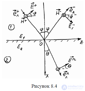
The path of the rays near the interface is shown for waves with parallel polarization in fig.4. In this case, the vectors  lie in the plane of incidence, and the vectors
 are directed parallel to the interface. Therefore, the boundary conditions for these vectors on the interface will look as follows:

Let us transform the second equality to the form:
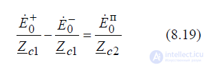
and then divide equalities (8.17) and (8.19) by  , as a result of which we arrive at the system of equations:
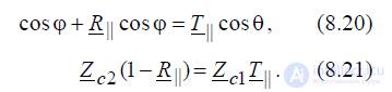
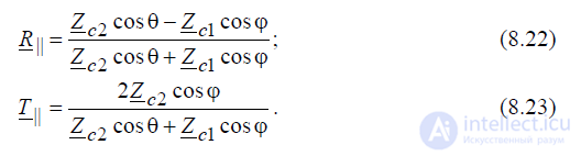
Solving these equations with respect to  , we obtain the Fresnel formulas for waves of parallel polarization:
For ideal dielectrics with μ1 = μ2, the last expressions transform to the form:
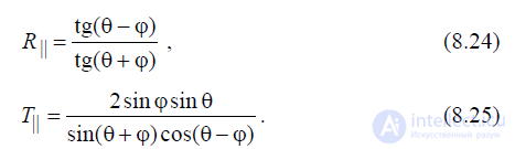
It is easy to show that in the case of normal incidence of a linearly polarized wave on the interface between two media (ϕ = π/ 2 ), the transmission and reflection coefficients are given by the following expressions:
 (8.26)
From this it follows that the reflection and transmission coefficients for waves with different polarization turn out to be identical, which is quite natural, since in this case the plane of incidence turns out to be undefined.
We will assume that the media on both sides of the interface are ideal non-magnetic dielectrics for which μ2 = μ1, σ = 0. Let us show that there exists an angle of incidence, called Brewster's angle,
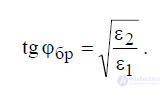
ϕ = ϕbr , at which the incident parallel-polarized wave is not reflected from the interface (reflection coefficient R|| = 0 ). It is easy to establish that in the case ε2 ≠ ε1 (i.e., θ ≠ ϕ) this condition will be satisfied only when the denominator of expression (8.24) tends to infinity, that is, tg(ϕ + θ)→∞ , from which it follows that ϕ + θ = π/ 2. Substituting θ = π/ 2 − ϕ into the 2nd Snell's law, we find the required Brewster angle:
 (8.27)
or
 (8.28)
From (8.28) it follows that Brewster's angle exists for any ratio between ε1 and ε2 , i.e., both for n2 > n1, and for n2 < n1.
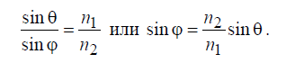
Let us consider in more detail the second case, when the electromagnetic wave passes from a denser medium into a less dense medium ( n1 > n2 , ε1 > ε2 ) and the following relation between the angle of incidence and the angle of refraction holds:
 . (8.29)
Since n2 / n1 <1, then sin θ > sin ϕ and θ < ϕ. From this one can find an angle of incidence ϕcr , called the critical angle, at which the refracted wave begins to slide along the interface (θ = π/2):
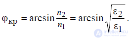 . (8.30)
At ϕ ≥ ϕcr the phenomenon of total reflection is observed 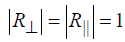 for waves of both polarizations. Typical plots of the dependences of the modulus and phase of the reflection coefficient are shown in fig.8.5 for two characteristic cases:
n2 > n1 (fig.8.5,a,c) and n1 > n1 (fig.8.5,b,d).
In calculating the plots mentioned, it was assumed that media 1 and 2 have the following parameters: ε1r = 4 , ε2r =1, μ1r = μ2r =1, σ1 = σ2 = 0.
An example of such use is an optical fiber (a modern transmission line of the optical wave range), which is a flexible dielectric rod inside which an electromagnetic wave propagates, held within the dielectric precisely due to the use of this effect, the effect of total internal reflection.
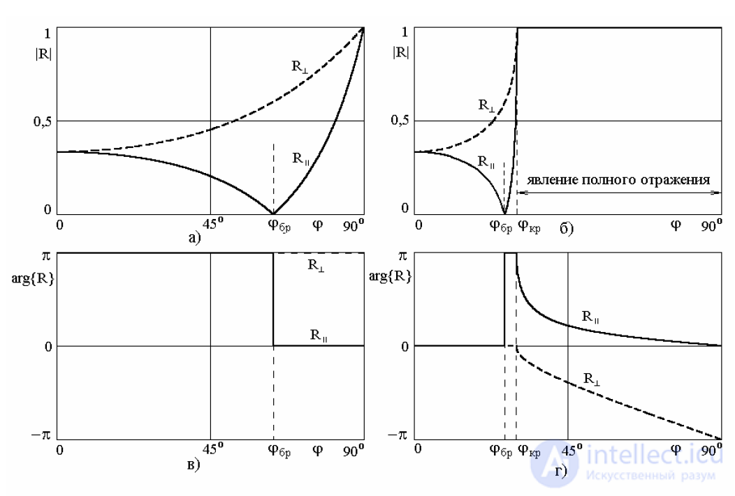
Figure 8.5.
It is easy to show that when a plane wave is incident on the interface at an angle ϕ > ϕcr , when the phenomenon of total internal reflection is observed, the moduli of the reflection coefficients for waves of both polarizations equal unity 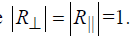 . This means that the incident wave is completely reflected from the interface, and the power carried by it is completely reflected back into the 1st medium and does not pass into the 2nd medium at all. At the same time, from formulas (8.23) and (8.25) it follows that at ϕ > ϕcr the transmission coefficients T⊥ and T|| are not equal to zero (T⊥ ≠ 0 and T|| ≠ 0 ), i.e., the field in medium 2 nevertheless exists. Therefore it makes sense to examine the structure of this field in more detail, assuming that it is described by expression (8.3), which, taking into account the notation adopted in fig.8.3
  , is written
in the form:
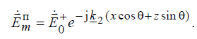 . (8.31)
From the law of sines it follows that, in the presence of total internal reflection, i.e., when ϕ > ϕcr , sin θ must be greater than unity:
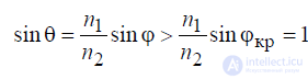 . (8.32)
which is in principle impossible if θ is understood as a real spatial angle of refraction. However, if we assume that the quantity θ = θ is complex, then the value of sin θ can exceed 1. Therefore let us accept this assumption and represent θ in the form:
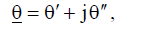 , (8.33)
where θ′ is the real part of θ, corresponding to the real spatial angle θ, and θ′′ – is the imaginary part of θ, whose physical meaning has yet to be clarified. Taking into account that at angles of incidence ϕ > ϕcr the refracted wave slides along the interface and the real angle of refraction equals θ = π/ 2 , let us find the values of sin θ and cosθ :

Taking (8.34)-(8.35) into account, formula (8.31) takes the following form:
 (8.36)
where
 (8.37)
Expression (8.36) describes a plane electromagnetic wave propagating along the z axis in the positive direction. The phase coefficient of this wave equals β2z = k2 ch θ′′ > k2 . The factor e−α2x x in (8.36) indicates an exponential decrease of the wave amplitude as the observation point moves away from the interface. Thus, expression (8.36) gives grounds to assert that in the 2nd medium there exists a plane inhomogeneous electromagnetic wave, propagating along the interface x = 0. Since the main part of the energy carried by this wave is also concentrated near the surface, such a wave is customarily called a surface wave. The appearance of this wave can be regarded as a manifestation of a certain “inertia” of the electromagnetic field upon total reflection of the wave from the interface.
Let us examine in more detail the phase coefficient β2z and the attenuation constant α2x of the surface wave. Using the law of sines (8.7), equalities (8.37) can easily be transformed to the following form:
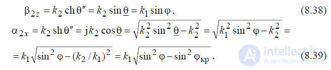
and also obtain a formula for determining the propagation velocity of the surface wave:
 . (8.40)
From the expressions obtained, it is evident that the parameters α2x , β2z and υ2z depend on the angle of incidence ϕ. The stronger the inequality ϕ > ϕcr , the greater the values of the phase coefficient β2z and the attenuation constant α2x , and the smaller the wave velocity υz . The latter, incidentally, has quite definite limits of variation: υ2 > υ2z > υ1 – from υz =υ2 at ϕ = ϕcr to υz =υ1 at ϕ = 90o .
Here, as before, υ1 and υ2 – are the propagation velocities of the electromagnetic wave in the 1st and 2nd media respectively (υ1 < υ2, since here n1 > n2 ) .
Now let us find the field in the 1st medium for the case of total internal reflection, which is formed by the superposition of two waves – incident and reflected.
Taking into account that in this case the reflection coefficient can be represented as  , let us write the sought field in the following form:
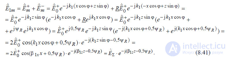
The field in medium 1, represented by expression (8.41), is an electromagnetic wave traveling along the z axis. The amplitude of this wave E&Σ depends on the transverse coordinate x and itself represents a standing wave along the x axis.
The phase constants β1z of the wave traveling along the z axis and β1x of the standing wave along the x axis are projections of the wave number k1 onto the corresponding coordinate axes:

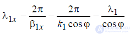
The length of the standing wave along the x axis, determined from the relation
 (8.42)
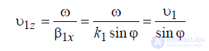
and the propagation velocity of the traveling wave
 z (8.43)
are dependent on the angle of incidence ϕ, and their values turn out to be larger compared to analogous ones in free space with the same parameters as the first medium.
Summarizing this section, it should be noted that a plane interface between two media, in the presence of the phenomenon of total reflection, transforms a plane homogeneous electromagnetic wave, incident on it from an arbitrary direction (ϕcr < ϕ < 90o ), into inhomogeneous electromagnetic waves and directs their motion along the interface. Thus, it can be considered that the interface in this case serves as a certain guiding system for the propagation of electromagnetic waves in both media. In this case, the propagation velocity of the wave in the 1st medium υ1z exactly coincides with the velocity of motion of the surface wave in the 2nd medium υ2z , which is clearly seen when comparing formulas (8.40) and (8.43).
Fig.8.6 shows typical distributions of the amplitudes of the waves existing in both media in the presence of the phenomenon of total internal reflection. The coordinate x here is normalized to the wavelength in the 1st medium. In constructing the plots, it was assumed that the 1st medium (optically denser) occupies the half-space x < 0, and the 2nd medium – the half-space x > 0 . The media themselves have the same parameters as in the case of fig.8.5. In the plots shown, it is clearly seen that in the 1st medium the amplitude distribution has the form of a standing wave, whose length increases with increasing angle of incidence ϕ. The amplitude of the surface
wave in the 2nd medium decreases aperiodically with distance from the interface ( x = 0 ) according to an exponential law, with the rate of this decrease increasing with increasing angle ϕ.
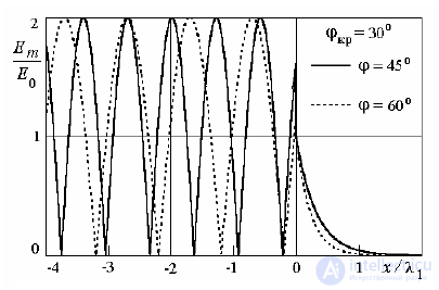
fig.8.6
Above, the nature of the phenomena accompanying the incidence of a plane electromagnetic wave on the flat interface between two ideal dielectrics was studied in detail. Now we will trace how the conductivity of the 2nd medium affects the characteristics of the reflected and refracted waves. We will assume that the 1st medium, in which the incident wave propagates, is an ideal
dielectric with parameters ε1 and μ1, and the second medium is conducting with parameters ε2 , μ2 and σ2 . The wave number of the 1st medium will be real k1 = β1, and the wave number of the 2nd medium – complex k 2 = β2 − jα2 . In this case, it follows from the law of sines that  , and likewise θ, is also a complex quantity. Denoting
  and taking into account that
 , let us write the field of the refracted wave in the 2nd medium:
 . (8.44)
Thus, the field in the absorbing medium is a traveling wave. The front (surface of equal phases) of the wave  is a plane inclined to the z axis at an angle
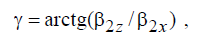 , (8.45)
which is at the same time the angle of refraction of the wave, since the direction of its motion coincides with the normal to its front. The surface of equal amplitude x = const is a plane parallel to the interface. Consequently, this wave can be classified as plane and inhomogeneous, since the surfaces of equal phases and amplitudes do not coincide.
The amplitude of the refracted wave, as it penetrates deeper into the conducting medium, decreases exponentially 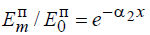 and at a depth
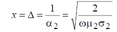
it decreases by a factor of e ≈ 2.71. In doing so, the wave loses a significant part of its power (about 86.5%). The higher the oscillation frequency ω and the greater the conductivity of the medium, the smaller the penetration depth Δ. Thus, a high-frequency electromagnetic field in a conductor is concentrated mainly near its surface. This phenomenon is called the surface effect (skin effect). The penetration depth Δ is often also called the skin-layer thickness in the literature (from the English word skin). To estimate the actual magnitude of the penetration depth, let us give one example. The penetration depth of a wave into copper, whose specific conductivity is σ = 5.7 ⋅107 S/m, at a frequency f = 10 GHz is Δ ≈ 0.6 µm.
Now let us assume that the 1st medium, as before, is an ideal dielectric, and the 2nd is a good conductor (for example, a metal), for which  , and in this case the conditions
  and
and 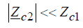 are satisfied. Using the 2nd Snell's law, it is easy to show that
  , and, consequently cosθ ≈1. Moreover, it is obvious
that in this case  , from which it follows that γ <<1.
This indicates that the direction of motion of the refracted wave in the metal differs little from the normal to the interface. Since this is so, the vectors 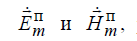
, located in the plane perpendicular to the direction of propagation, are themselves the tangential components with respect to the interface, and consequently, the following relation can be written for them:
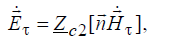 (8.46)
which is called the approximate Leontovich–Shchukin boundary condition Z c2 = (1+ j) /(Δσ) . From it, it follows that at the surface of a real metal the tangential component of the electric field is very small, since the characteristic impedance Z c2 of a good conductor is a very small quantity. However, in a number of cases this field component cannot be neglected, especially when the calculation of the power of thermal losses of the electromagnetic field is concerned. The fact is that it is precisely the tangential components of the fields that determine the magnitude of the power flux density penetrating through the surface into the interior of the conductor and dissipated in it. Indeed, the complex Poynting vector, directed into the conductor, in this case has the form:

.
Knowing the density of the Poynting vector, it is easy to find the power loss in the conductor:
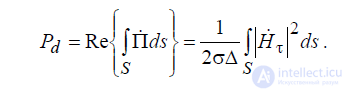
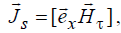
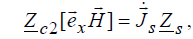
Now let us show that the characteristic impedance of the conductor Zc2 , is at the same time its surface impedance S Z, consequently. To do this it is necessary to assume that the conductor is ideal and that inside it there are no electric or magnetic fields, and that a conduction current flows along its surface, whose surface density equals  . This conduction current is caused by the presence of the tangential component of the electric field
  and is related to it by Ohm's law, which in this case can be written in the form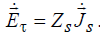
Substituting here  from (42) and, taking into account the boundary conditions for the tangential component of the magnetic field
, we have:
 , (8.47)
From which the equality follows:

indicating that the surface resistance of the conductor coincides with its characteristic impedance.
Let us now estimate the reflection coefficients from a metal for waves of different polarization, assuming that their angle of incidence ϕ is noticeably different from 90°:

The better the conductor, the smaller the ratio Z c2 Zc1 and the closer the reflection coefficients are to 1. It is easy to show that in the limiting case, when the 2nd medium becomes an ideal conductor, for which σ2 →∞ and Zc2 = 0, the reflection and transmission coefficients will not depend on the angles of incidence ϕ and will equal:

Let us consider the incidence of a plane electromagnetic wave on the interface between two media, lying in the plane x = x0 . We will assume that medium 1 is an ideal dielectric, and the incident wave moves normal to the interface, i.e., the angle of incidence ϕ = 0. Then the fields of the incident and reflected waves can be described by the following expressions:
 . (8.50)
Let us find the complex amplitude of the reflected wave  , assuming that the amplitude of the incident wave
  and its reflection coefficient R from the interface x = x0 are known to us:

Substituting here the values of the field strengths of the incident and reflected waves, we have:
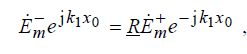
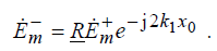
From which we find:
 (8.51)
Now, knowing − m E& , expression (8.50) can be written in the form:
 . (8.52)
The dependence of the electric field strength of the reflected wave on time will look as follows:
 , (8.52)
where 
Now let us assume that the plane x = x0 , separating the two different media, moves along x with velocity V0 , significantly smaller than the velocity of wave motion in the 1st medium υ1 =1/ ε1μ1 . Then the position of the interface plane will change with time according to a linear law x0 =V0t , and the dependence of the field strength on time will take the following form:

If the interface moves along the x axis in the positive direction, i.e., moves away from the source of the electromagnetic wave  , then Ω > 0 and ω1 = ω−Ω < ω.
In the case when the interface moves toward the source of the waves, i.e., approaches it, then  hence Ω<0 and ω1=ω0 – Ω>ω0.
The phenomenon of change in the frequency of an electromagnetic wave upon its reflection from the interface between two media, moving along the direction of wave propagation, is called the Doppler effect, and the quantity Ω, by which the frequency of the reflected wave differs from the frequency of the incident wave, is called the Doppler frequency.
The flat interface between two media in the problem considered played the role of a certain reflector, from which the primary incident wave was reflected. Any moving body or surface capable of reflecting electromagnetic waves, for example an airplane, a car, a ship, or a person, can in principle play the same role. Therefore the Doppler effect is widely used in engineering, in particular in radiolocation, for detecting and selecting moving objects.

Comments