
Lecture
In anisotropic media, which include magnetized ferrites and plasma, new properties of EM waves appear – significant differences in the conditions of propagation of EM waves in the forward and reverse directions in a transmission line. Ferrite possesses the magnetic properties of a ferromagnet and the electrical properties of a dielectric. This is achieved by mixing ferromagnetic particles with a dielectric material during manufacture. The EM field, penetrating into the dielectric, interacts with the ferromagnet.
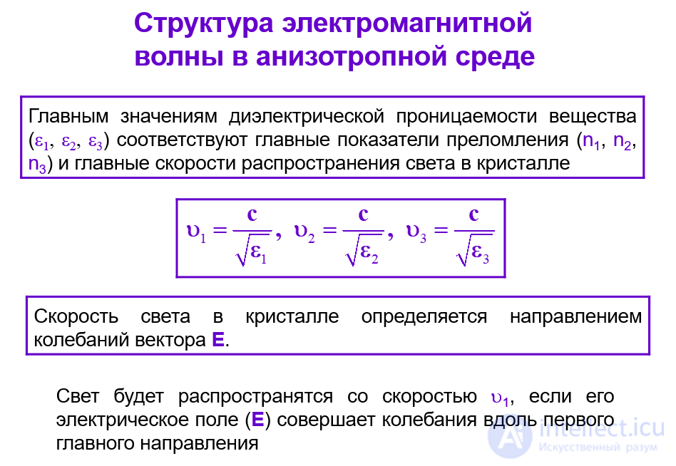
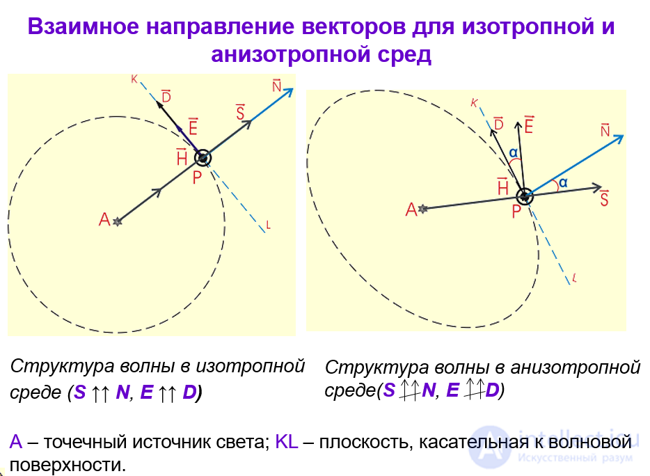
Quantities characterizing the structure of an electromagnetic wave at each observation point
So far we have considered a plane wave propagating along the direction of the oz axis, i.e. a wave for which the planes of equal phase are perpendicular to the oz axis.
However, the direction of propagation may not coincide with the oz axis, and the plane of equal phase may be tilted relative to this axis, for example as shown in fig. 1.
In this case, instead of , the equation of the plane of equal phase will be

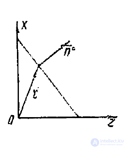
Fig. 1
It follows from this that the direction of propagation of a plane wave can be characterized either by the normal n° to the plane of equal phase, or by the vector  , called the wave vector.
In what follows we shall consider a plane wave with an arbitrary direction of propagation, and we shall denote this direction by the vector n°.
Bearing in mind that we intend to study the propagation of plane waves in an anisotropic medium, whose permittivity is a tensor, in Maxwell's equations we shall retain the electric
displacement vector D, without replacing it, as in the case of an isotropic medium, by the expression  .
.
So we shall proceed from Maxwell's equations

and we shall seek their solution, corresponding to plane waves, in the form
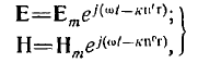 (1)
(1)
where  , and the propagation constant k — is an unknown quantity and is to be determined.
Making use of the vector relation

where A — is a constant vector and φ — is a scalar function, after substituting (1) into Maxwell's equations we obtain
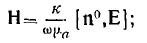 ; (2)
; (2)
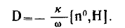 . (3)
. (3)
From these relations it follows that the vector H is perpendicular to the vectors E and n°, while the vector D is perpendicular to H and n°.
Since, however, in the case of an anisotropic medium the vector D is not collinear with the vector E, it follows that the vector E is not perpendicular to the direction of wave propagation.
On the other hand, the Poynting vector, defined by the formula
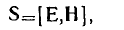
, is perpendicular to the vectors E and H. It follows from this that the velocity of the direction of propagation, i.e. the phase velocity, which is directed along the vector n°, does not coincide with the velocity of energy propagation, which is directed along the Poynting vector.
Consequently, in anisotropic media it is necessary to distinguish two velocities — the phase velocity  and the velocity
  along the direction of the Poynting vector, called the ray velocity.
The phase velocity is determined by the well-known relation
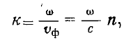
where n — is the refractive index.
Substituting this expression for k into relations (2) and (3), we obtain
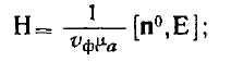 (4)
(4)
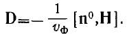 . (5)
. (5)
Taking these relations into account, let us find expressions for the electric field energy density  and the magnetic field energy density
  .
.
We have
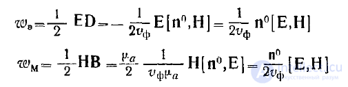
and, consequently, the energy density of the electromagnetic field is equal to
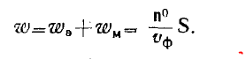
From this we find
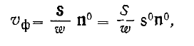
where s0 — is the unit vector in the direction of the Poynting vector.
The quantity 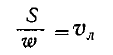 is the ray velocity of the wave. *
Thus, we obtain
 , (6)
, (6)
where α — is the angle between the vectors s0 and n°.
We note that

So, the process of propagation of a plane wave in an anisotropic medium is characterized by 5 vectors E, D, H, n°, s0, with the vector H perpendicular to all the other vectors.
It follows from this that the vectors E, D, n°, s° are coplanar, i.e. lie in a single plane. The orientation of all the vectors relative to one another is clear from fig. 2.
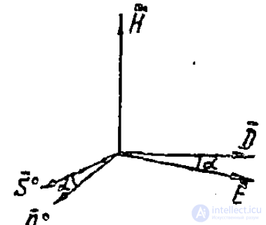
Fig. 2
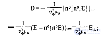
Substituting the vector H from relation (4) into relation (5), we find
 , ; (7)
n°(n°E) — this is the longitudinal component of the vector E along the direction n°;
 — is the transverse component of the vector E with respect to the same direction.
The relation
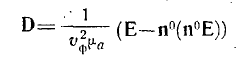 (8)
(8)
is precisely the sought vector equation for determining the phase velocity V_ph in an anisotropic medium.
Let us find an analogous equation for determining the ray velocity v_l.
Since  , then, as can be seen from fig. 2, the transverse component of the vector E with respect to the vector n° equals the longitudinal component of this same vector along the vector D, i.e.
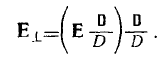
Substituting this expression for  x into (7), we obtain
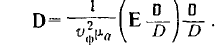
Taking the scalar (dot) product of both sides of this equality with D, we find
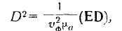 ,
,
that is
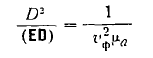
or
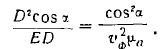
Taking formula (6) into account here, we obtain
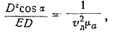
or
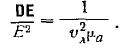
Further, taking into account that the transverse component of the vector D with respect to s0 equals the longitudinal component of this vector along
E, i.e.

we find
 . (9)
. (9)
This is precisely the sought vector equation for determining the ray velocity v_l.
Formulas (8) and (9) are a consequence of Maxwell's equations and therefore do not depend on the properties of the medium.
Let us now include material equations in our consideration.
Let us choose as coordinate axes the principal directions of the permittivity tensor. In this case the relations turn out to be quite simple.
Let us introduce, as before, the notation  , and replace the indices x, y, z with the numbers 1, 2, 3.
Then the vector equation (8) is represented by the following 3 scalar equations
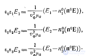
Denoting 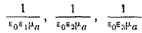 respectively by the expressions
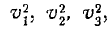 this system of equations can be represented in the form
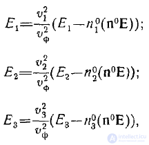
from which we obtain

Multiplying the left and right sides of these equalities by 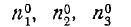 , respectively, and adding them, we find
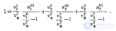
We subtract 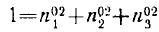 from the left and right sides and finally obtain
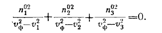 . (10)
This is the so-called equation of the wave normals with respect to the square of the phase velocity  The equation is quadratic, as can be verified by multiplying it by the product
 .
.
Thus, we find that the structure of an anisotropic medium permits the propagation, in any given direction, of two plane linearly polarized waves (there is no phase shift between the field
components), propagating with different phase velocities, and each of these waves can propagate in two opposite directions.
Under the same conditions as adopted in the preceding section, let us represent vector equation (9) as three scalar equations and obtain
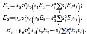
From this
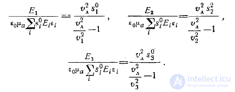
Multiplying the left and right sides of these equalities by 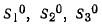 respectively and adding them, on the left we will have 0, and as a result we obtain the equation
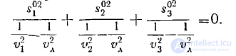
This is — a quadratic equation with respect to 
Consequently, each direction of the vector s0 corresponds to two different values of the square of the ray velocity.
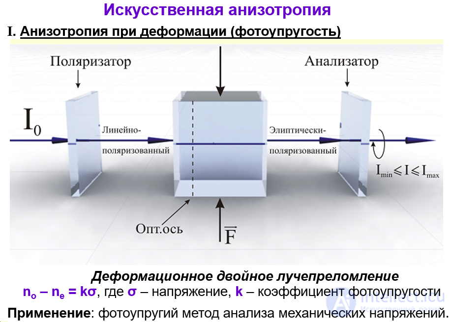
I. Anisotropy under deformation (photoelasticity)
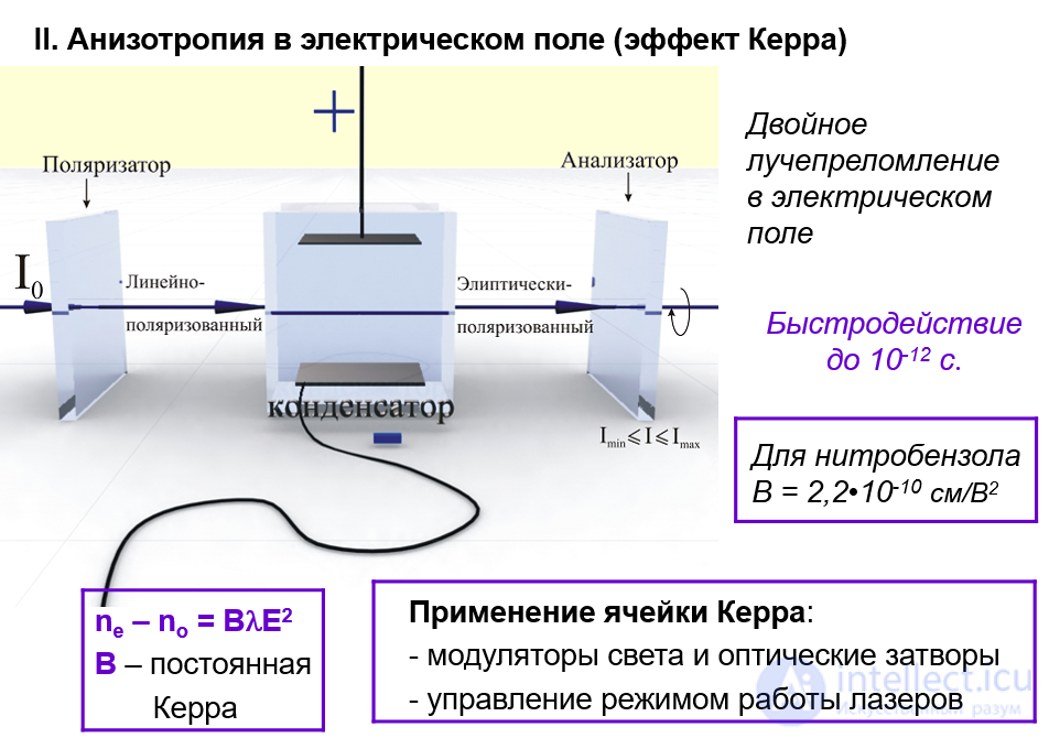
II. Anisotropy in an electric field (the Kerr effect)

Comments