
Lecture
Active dielectrics are those whose properties can be controlled by external energy influences, and these influences can be used to create functional electronic elements. Active dielectrics make it possible to generate, amplify, and modulate electrical and optical signals, and to store or transform information. As electronic equipment grows more complex and moves toward functional electronics, the role and importance of active materials in solving key scientific and technical problems continuously increases.
Active dielectrics include ferroelectrics, piezoelectrics, and pyroelectrics; electrets; quantum-electronics materials; liquid crystals; electro-optical, magneto-optical, and acousto-optical materials; dielectric crystals with nonlinear optical properties, and others. The properties of active dielectrics can be exhibited not only by solids but also by liquid and even gaseous substances (for example, the active medium of gas lasers). By chemical composition, these can be organic and inorganic materials. By structure and properties, they can be divided into crystalline and amorphous, polar and nonpolar dielectrics. A number of materials display their activity only because of the presence of spontaneous or stable residual polarization in them. However, a polarized initial state is not a mandatory condition for a material to exhibit activity under external influences. A strict classification of active dielectrics, covering the many distinguishing features of these materials, turns out to be quite difficult. Moreover, there is no sharp boundary between active and passive dielectrics. The same material, under different operating conditions, can perform either the passive function of an insulator or capacitor, or the active function of a controlling or converting element.
Of the whole variety of active dielectrics, this chapter considers only those that have found the widest practical application.
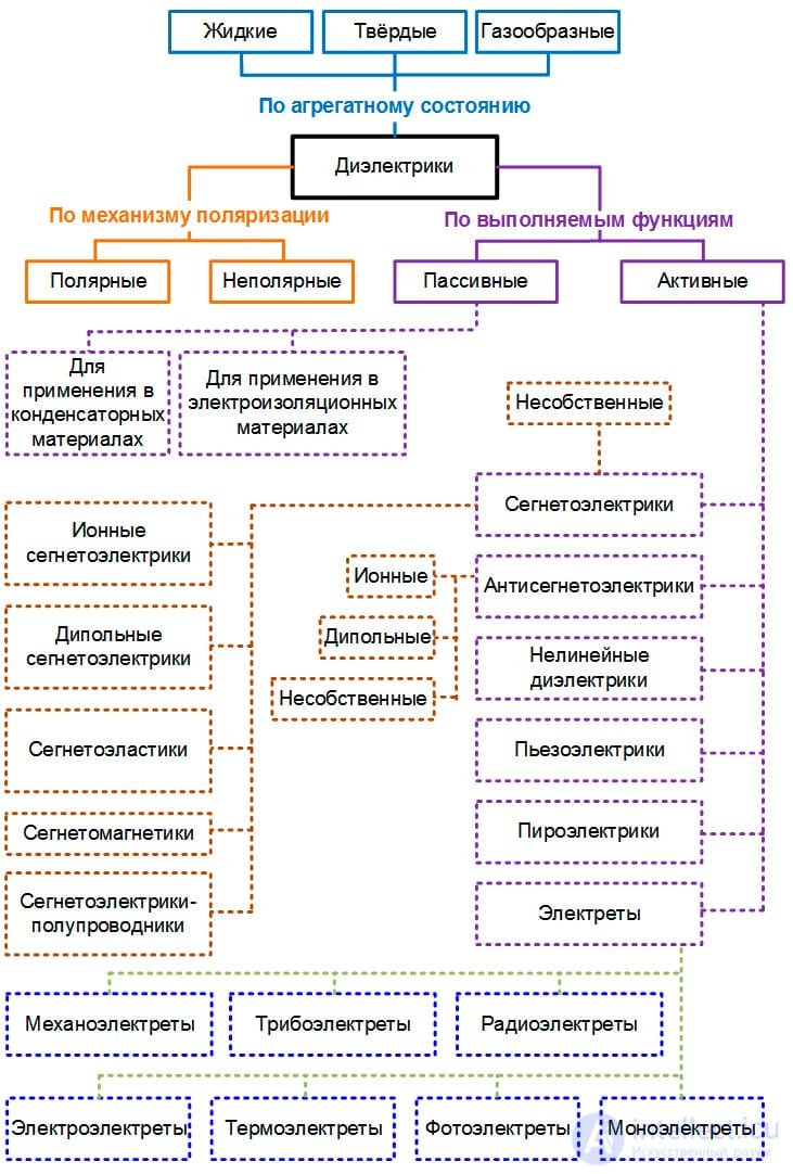
Figure 1 – Classification of dielectrics
Active dielectrics include ferroelectrics, piezoelectrics, electrets, quantum-electronics materials, superionic conductors, and others. A strict classification of active dielectrics is impossible, since the same material can exhibit features of various active dielectrics. Thus, ferroelectrics often combine the properties of piezoelectrics. Moreover, there is no sharp boundary between active and passive dielectrics. The same material, depending on the operating conditions, can perform either the function of a passive insulator or the active functions of a converting or controlling element.
Ferroelectrics are materials that possess spontaneous polarization, the direction of which can be changed by an external electric field.
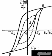
Figure 1 Polarization curve of a ferroelectric and the dielectric hysteresis loop.
In the absence of an external electric field, ferroelectrics generally have a domain structure, that is, they break up into microscopic regions possessing spontaneous polarization. In principle, ferromagnets also have domains — regions of spontaneous magnetization — so the behavior of ferroelectrics in an electric field is similar to the behavior of ferromagnets in a magnetic field. The only difference between ferroelectrics and ferromagnets is that when they are placed in an electric field, the electric displacement vector D = E + P changes, whereas for ferromagnets placed in a magnetic field, the induction B = H+I changes.
Abroad, ferroelectrics are called ferroelectrics [ferroelectrics], since ferroelectrics are the formal analogs of ferromagnets.
The domestic name — ferroelectrics [segnetoelectrics] — comes from Rochelle salt, the double potassium-sodium salt of tartaric acid (NaKC4H4O6). Rochelle salt was the first material in which spontaneous polarization was discovered. The properties of Rochelle salt were comprehensively studied by I.V. Kurchatov together with P.P. Kobeko in the early 1930s. Rochelle salt single crystals found wide application in the manufacture of various devices during the Great Patriotic War, but today Rochelle salt has lost its technical significance due to its low moisture resistance and poor mechanical properties. Fundamental and applied work on ferroelectricity began to develop very intensively after B.M. Vul discovered (1944) the ferroelectric properties of barium titanate BaTiO3.
Using BaTiO3 as an example, let us examine the structure and properties of ferroelectrics.
The chemical bonds in BaTiO3 are ionic-covalent. Barium titanate crystallizes into a perovskite-type structure. The unit cell of this type of lattice can be represented as follows: the basis of the structure consists of oxygen octahedra, at the center of which are located titanium ions. In turn, the oxygen ions center the faces of the cube formed by the barium ions (Fig. 2).
The dimensions of the unit cell are larger than the doubled sum of the ionic radii of the titanium and oxygen ions. Therefore, the titanium ion has some freedom of movement within the oxygen octahedron.
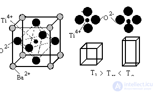
Figure 2. The crystal lattice of barium titanate, and the deformation of the lattice at the transition through the Curie point.
At sufficiently high temperatures, the thermal energy of the titanium ion is sufficient for it to continuously hop from one oxygen ion to another, so the average position of the titanium ion is at the center of the unit cell, and the unit cell is symmetric — cubic.
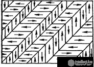
Figure 3. Division of a ferroelectric crystal into domains.
A decrease in temperature leads to a decrease in the kinetic energy of the titanium ion, and at a certain temperature (below 120 °C) it becomes localized near one of the oxygen ions. As a result, the symmetry in the arrangement of the charged particles is broken, and the unit cell acquires a dipole moment. In the neighboring unit cell, the titanium ion shifts toward the negative pole of the resulting dipole. Thus, neighboring unit cells become spontaneously polarized.
Simultaneously with the spontaneous polarization, the crystal lattice deforms, and the cubic lattice becomes rhombohedral.
Thus, below a certain temperature (the Curie temperature), ferroelectrics spontaneously polarize, and their crystal lattice deforms in the process. Above the Curie temperature, ferroelectrics transition into the paraelectric state, and the crystal lattice becomes symmetric. The change in the type of crystal lattice at the transition through the Curie point is commonly called a phase transition.
The formation of domains in ferroelectric crystals is related to the fact that when all neighboring unit cells of the crystal are polarized in the same direction, an external electric field appears around the crystal. The presence of an electric field raises the energy of the system, and to lower the energy, the crystal spontaneously breaks up into domains.
Since the symmetry of the crystal lattice decreases below the Curie temperature, the number of directions along which spontaneous polarization of neighboring crystal lattices is favorable is comparatively small. Such directions will be directions of the <111> type. Accordingly, neighboring domains can be misoriented by 180 or by 90 degrees. Since the total electric moments of neighboring domains are antiparallel or perpendicular, the ferroelectric crystal as a whole has no electric moment.
It is important to note that at the domain boundaries there is a gradual rotation of the dipole moments from one direction to another, similar to how this rotation occurs in ferromagnets. This is yet another similarity between ferroelectrics and ferromagnets. Evidently, the domain boundaries in ferroelectrics interact with structural imperfections of the lattice in the same way as in ferromagnets.
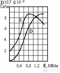
Figure 4. Dependence of the electric displacement vector D and the permittivity e on the electric field strength E
When a ferroelectric is placed in an electric field, some domains have minimal energy since their dipole moments coincide with the direction of the field. To lower the total energy of the material, these domains grow, and the total polarization of the ferroelectric increases (Fig. 4). Once the favorably oriented domains fill the entire crystal, the growth of polarization stops.
It is known that the permittivity is the ratio of the electric displacement vector to the electric field strength vector e=D/E. Thus, in the region of sharp polarization growth, the permittivity of ferroelectrics is at its maximum.
This dependence of the permittivity of ferroelectrics on the electric field strength allows such materials to be used to make electric field strength sensors and varicaps – nonlinear capacitors whose capacitance depends on the applied voltage.
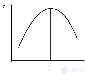
Figure 5 Change in the permittivity of ferroelectrics with increasing temperature
Temperature also has a significant effect on the behavior of dielectrics in an electric field. As noted earlier, upon reaching a certain temperature, ferroelectrics transition into the paraelectric state. This temperature is called the Curie temperature. Let us examine the effect of temperature on the properties of ferroelectrics in more detail, again taking barium titanate as an example. As temperature increases, the kinetic energy of the ions increases, and the interaction between the oxygen and titanium ions that form the dipole moments weakens. Therefore, the rotation of the dipoles becomes easier, and the maximum polarization is observed at lower values of the electric field strength. Consequently, the permittivity of ferroelectrics increases. When the electrostatic interaction energy of the oxygen and titanium ions equals the kinetic energy of the titanium ion vibrations, the ferroelectric transitions into the paraelectric state. At this point, the permittivity reaches its maximum. A further increase in temperature causes the thermal vibrations to misorient the dipoles, and the permittivity decreases.
Two important features of ferroelectrics follow from the above discussion. First, ferroelectrics can be used to make temperature sensors. Second, changing the electrostatic interaction energy between ions and changing the mass of the ions through doping makes it possible to change the Curie temperature. This last circumstance makes it possible to create materials with a diffuse Curie point, so that over a fairly wide temperature range the ferroelectric will have a sufficiently high permittivity, which allows such materials to be used to make high-capacitance capacitors.
In addition, changing the Curie point through doping makes it possible to manufacture compensating capacitors whose capacitance changes with heating and compensates for the change in capacitance of other capacitors.
As an illustration of the effect of doping on the properties of ferroelectrics, let us consider doping barium titanate with barium zirconate and calcium titanate.
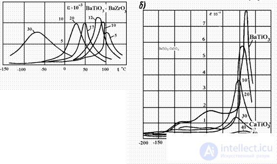
As can be seen from the figures given, doping leads to a significant change in the properties of ferroelectrics, so materials with various properties are manufactured on the basis of solid solutions.
Ferroelectric capacitor ceramics. To manufacture ferroelectric capacitor ceramics, additives are used that "smear" the ferroelectric phase transition, which leads to a smoothing of the temperature dependence of the permittivity. It should be noted, however, that smoothing the dependence of permittivity on temperature leads to a decrease in permittivity.
Among the existing capacitor ferroelectric ceramics, the following can be distinguished:
1. Materials with a weakly pronounced dependence of permittivity on temperature. A typical example is the T-900 ferroelectric ceramic. This material is a solid solution of strontium and bismuth titanates. The maximum permittivity corresponds to a Curie point of -140°C. In the operating temperature range (-50 to +150°), the temperature dependence of the permittivity is slightly decreasing. The average value of e is 900.
2. Materials with a smoothed dependence of permittivity on temperature. A typical representative of this class of ferroelectric ceramics is CM-1. This ferroelectric ceramic is obtained on the basis of barium titanate with the addition of zirconium and bismuth oxides. The material is used to make small-sized capacitors for low voltages.
3. Materials with a maximum permittivity value in a given temperature range. A typical representative is the material T-8000. This material is a solid solution of BaTiO3 – BaZrO3. The maximum permittivity is in the region of room temperature and amounts to 8000. It is used to make capacitors for room temperature operation over a narrow temperature range.
Ferroelectric ceramics for varicaps. Varicaps are nonlinear capacitors whose capacitance depends on the electric field strength. One of the most important characteristics of varicaps is the nonlinearity coefficient K – the ratio of the maximum permittivity value to the initial permittivity. The nonlinearity coefficient for various materials ranges from 4 to 50. The main crystalline phase in such materials is solid solutions of the Ba(Ti,Sn)O3 or Pb(Ni,Zr,Sn)O3 systems.
Ferroelectrics with a rectangular hysteresis loop shape. Owing to dielectric hysteresis, ferroelectrics can be used to record information. Polarization in one direction means storing a one in memory, while polarization in the other direction means storing a zero. For these purposes, materials with a hysteresis loop close to rectangular are most suitable. A rectangular hysteresis loop is observed in single-crystal ferroelectrics.
In 1880, the brothers P. and J. Curie discovered the direct piezoelectric effect – the appearance of electrostatic charges on a plate cut from a quartz crystal under the action of mechanical stress. These charges are proportional to the mechanical stress, change sign together with it, and disappear after the stress is removed.
Along with the direct piezoelectric effect, the converse piezoelectric effect is also observed, in which a mechanical deformation of the crystal arises under the action of an electric field, with the magnitude of the mechanical deformation directly proportional to the electric field strength.
The converse piezoelectric effect should not be confused with electrostriction – the deformation of dielectrics under the action of an electric field. Electrostriction is observed both in solid and liquid dielectrics, whereas the piezoelectric effect is observed only in solid dielectrics with a specific crystal structure. In addition, electrostriction exhibits a quadratic dependence between field strength and deformation, while the piezoelectric effect exhibits a linear dependence.
The piezoelectric effect is observed only when the crystal lattice is asymmetric. The absence of a center of symmetry in the crystal lattice is a necessary but not sufficient condition for the appearance of the piezoelectric effect.
As noted above, in the direct piezoelectric effect, the charges on the surface of the dielectric are proportional to the applied force.
 ( 1)
( 1)
Where Q – is the magnitude of the charge, F – is the magnitude of the applied force, d is the proportionality coefficient between the charge and the applied force, called the piezoelectric modulus.
 ( 2)
( 2)
Dividing the magnitude of the charge and the applied force by the area S, we get
or  ( 3)
( 3)
where: qs – surface charge density, Р – polarization, s - mechanical stress.
For the case of the converse piezoelectric effect, the piezoelectric modulus relates the value of the relative deformation of the crystal to the electric field strength
 ( 4)
( 4)
It is important to note that the relations given are only of a qualitative character. The actual description of the piezoelectric effect is much more complex. The point is that mechanical stress is a tensor quantity having six independent components, whereas polarization is a vector quantity. Therefore the piezoelectric modulus, which establishes the relationship between the polarization vector and mechanical stresses, is a third-rank tensor having 18 independent components. In tensor form, the equations of the direct and converse piezoelectric effects take the following form:
 ( 5)
( 5)
 ( 6)
( 6)
where i = 1,2,3 – components of the polarization vector; j = 1,2…6 – components of the tensor of mechanical stresses or strains.
In addition to the piezoelectric modulus, another important characteristic of piezoelectrics is the electromechanical coupling coefficient k. The square of this coefficient represents the ratio of the mechanical energy to the total electrical energy received from the power source.
Piezoelectric materials
A large number of substances possessing piezoelectric properties are currently known, including all ferroelectrics. However, not all piezoelectric materials have found technical application.
One of the best-known piezoelectrics is monocrystalline quartz – anhydrous silicon dioxide, which crystallizes in the trigonal-trapezohedral class of the hexagonal system. Large natural transparent quartz crystals are called rock crystal. In quartz crystals it is customary to distinguish three principal axes: Х – the axis passing through the vertices of the hexagonal cross-section (there are 3 such axes); Y - the axis perpendicular to the sides of the hexagonal cross-section (there are also three such axes); Z – the axis passing through the apices of the crystal.
Quartz plates cut perpendicular to the Z axis do not exhibit the piezoelectric effect. The greatest effect is observed in plates cut perpendicular to the Х axis.
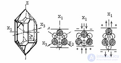
Figure 7 Quartz crystal and diagram of the origin of the piezoelectric effect.
A plane-parallel polished quartz plate with electrodes and a holder constitutes a piezoelectric resonator, that is, it is an oscillatory circuit with a definite resonant frequency of vibration. The resonant frequency depends on the thickness of the plate and the direction of the cut. The advantages of quartz resonators are a small tgd and a high mechanical Q-factor. Owing to their high mechanical Q-factor, quartz resonators are used as filters with high selectivity, and also for frequency stabilization and referencing in oscillators. One of the most important requirements for such resonators is temperature stability of the resonant frequency. This requirement is met by plates with special oblique cuts relative to the principal axes.
Natural quartz crystals, as a rule, contain defects that reduce their value. Therefore the main needs of piezoelectric technology are met by artificial crystals grown from silicon-saturated alkaline solutions.
Besides quartz, lithium niobate and lithium tantalate are widely used as materials for piezoelectric elements. By their nature, these materials are ferroelectrics. To impart piezoelectric properties to them, they are annealed in a strong electric field, which leads to the creation of a single-domain state.
In a similar way, ferroelectric ceramics can be converted into a piezoelectric state. Polarized ferroelectric ceramics are called piezoceramics. Piezoceramics have the advantage over single crystals that an active element of any shape and size can be made from them. Solid solutions based on barium titanate, lead zirconate titanate, and lead metaniobate are used as materials for piezoceramics.
Piezoceramic materials are customarily divided into four functional groups. Group 1 materials are used to produce highly sensitive elements operating in the mode of receiving or emitting mechanical vibrations. For such materials a large piezoelectric modulus is required. Group 2 materials are used to produce strong-signal generators operating under conditions of strong electric fields or high mechanical stresses. For such materials a high electrical resistivity is required. Group 3 materials are used to produce piezoelements possessing increased stability of resonant frequencies with respect to temperature and time. Group 4 materials are used to produce high-temperature piezoelements.
Materials based on barium titanate. The cheapest material is piezoceramic ТБ-1 (BaTiO3). The absence of components volatile during firing and the simplicity of the manufacturing technology account for its wide use. Solid solutions of barium and calcium titanates with a cobalt addition (ТБК-3) and of barium, calcium, and lead titanates (ТБКС) have greater temperature stability of characteristics.
Materials based on solid solutions of lead zirconate titanate. Based on these solid solutions, a series of piezoelectric materials has been developed, bearing the conventional designation ЦТС (abroad, PZT). The composition of these materials is based on a solid solution containing 53-54% lead zirconate and 46-47% lead titanate. To improve the characteristics, strontium titanate additives are introduced into the base solution, as well as a number of oxides – oxides of niobium, tantalum, lanthanum, neodymium, and others.
The Curie temperature of these materials exceeds 250 °C, and they have no low-temperature phase transitions, which leads to high stability of the dielectric permittivity and piezoelectric modulus compared with the characteristics of ceramics based on lead titanate. The technology for producing ЦТС articles is complicated by the fact that ЦТС contains volatile lead oxide, which evaporates during firing. This circumstance leads to poor reproducibility of properties, so the firing of piezoelement blanks is carried out in an atmosphere of lead oxide vapor.
Materials based on lead metaniobate. Solid solutions of lead and barium metaniobates ((Pb,Ba)Nb2O3), containing 40-50% barium metaniobate, have a high Curie point temperature (above 250 °C); they also have no low-temperature phase transitions. The manufacturing technology for products made from them is simpler, so materials of the НБС grades have become widely used.
The properties of some piezoceramic materials are given in table 1.
Table 1 Characteristics of various piezoceramics.
|
Material grade |
Functional group |
Dielectric permittivity |
Curie point, °C |
Electromechanical coupling coefficient |
Piezoelectric moduli (d) 10-11, C/N, not less than |
|
|
|
|
|
|
|
d31 |
d33 |
|
ТБ-1 |
1 |
1500±300 |
110 |
0,20 |
4,5 |
10 |
|
ТБК –3 |
2 |
1200±200 |
95 |
0,2 |
4,3 |
8,3 |
|
ТБКС |
3 |
450±50 |
150 |
0,17 |
2 |
5 |
|
ЦТС 19 |
1 |
1725±325 |
290 |
0,4 |
10,0 |
20,0 |
|
ЦТСНВ-1 |
1 |
2250±560 |
240 |
0,45 |
16,5 |
40,0 |
|
ЦТС-23 |
2 |
1075±225 |
275 |
0,43 |
10,0 |
20,0 |
|
ЦТС-24 |
2 |
1075±225 |
270 |
0,45 |
10,0 |
20,0 |
|
ЦТБС-3 |
2 |
2300±500 |
180 |
0,45 |
12,5 |
32,0 |
|
ЦТСС-1 |
2 |
1150±150 |
260 |
0,43 |
7,5 |
18,0 |
|
ЦТС-22 |
3 |
800±200 |
300 |
0,20 |
2,0 |
5,0 |
|
ЦТС-35 |
3 |
1000±200 |
300 |
0,38 |
7,0 |
Not normalized. |
|
ЦТС-21 |
4 |
550±150 |
400 |
0,2 |
2,7 |
6,7 |
|
НБС 1 |
2 |
1600±300 |
245 |
0,28 |
6,7 |
16,7 |
|
НБС-3 |
3 |
1800±400 |
250 |
0,20 |
4,5 |
10,0 |
Electrets are dielectrics that retain an electrified state for a long time after the external influence that caused the electrification has ceased. Electrets are formal analogs of permanent magnets, which create a magnetic field around themselves. The fundamental possibility of obtaining such materials was predicted by Faraday. The term «electret» was proposed by Heaviside in 1896 by analogy with the English «magnet» – permanent magnet, and the first electrets were produced by the Japanese researcher Eguchi in 1922. Eguchi cooled a melt of carnauba wax and rosin in a strong electric field. The electric field oriented the polar molecules, and after cooling the material remained in a polarized state. To specify the technology, such materials are called thermoelectrets.
There are also other technologies for producing electrets. Electroelectrets are obtained by holding dielectrics in strong fields at room temperature. In this process the electric field tears electrons away from one surface of the material and supersaturates the other surface with them.
Photoelectrets are produced by the simultaneous action of an electric field and light. Irradiating the material with light excites the atoms and lowers the electron work function.
Corona electrets are produced by subjecting a dielectric to a corona discharge. In the corona discharge, one surface of the dielectric becomes saturated with ions of one sign, and the opposite surface becomes saturated with ions of the other sign.
Radioelectrets are produced by exposure to beams of high-energy charged particles.
Triboelectrets are produced by subjecting them to friction. The breakup of molecules under friction leads to an asymmetric arrangement of charges.
The production of electrets thus amounts to the electrification of a dielectric, resulting in the formation of large and time-stable charges, surface potentials, and electric fields. This problem can be solved either by obtaining a «frozen» polarization or by obtaining high concentrations of excess non-equilibrium, uncompensated charges.
The relative effectiveness of each of these approaches can be estimated on the basis of the following approximate calculation. Suppose a polar polymer with density (r) 103 kg/m3 and molecular mass (m) 102 kg/mol is chosen as the dielectric to be electrified. Then a unit volume contains rNA/m particles, where NA = 6´1026 kmol-1 is Avogadro's number. If we assume that the electric moment of each particle is 10-29 C´m and all particles are oriented in the direction perpendicular to the surface of the electret, then the surface charge density would be 6 10-2 C´m-2. This value exceeds the experimentally observed values of surface charge density by roughly a factor of 600. Consequently, to obtain the experimentally observed values of electric charge density, it is enough for one dipole out of 600 to be oriented.
If we assume that the surface charge density is created not by dipoles but by charged particles (e=1.6 10-19 C), then to obtain the actually observed values of surface electric charge density there must be 6.25 10-14 m-2 particles. In total there are rNA/m2/3, or 3.3 1018, particles on the surface of the dielectric. Consequently, to obtain the experimentally observed charge density, it is enough for one particle out of 5000 to be charged.
From this estimated calculation it is evident that it is more expedient to produce an electret by introducing charged particles into the dielectric.
It is important to note that if the surface charge density values were determined by the dielectric strength of the material, the stored charge would be substantially greater than that actually observed. Restrictions on the charge density are imposed by the electrical conductivity of the dielectrics and by the redistribution of charge through the thickness over time. Polar dielectrics have a higher electrical conductivity than non-polar ones. This is because the molecules of polar dielectrics actively attract impurity ions to themselves, so the concentration of charge carriers in polar dielectrics is always higher than in non-polar ones. Therefore electroelectrets, photoelectrets, corona electrets, and radioelectrets, which are usually produced from non-polar materials, have greater stability over time than thermoelectrets.
Unlike ordinary dielectrics, in which electric induction and polarization disappear quickly after removal of the external electric field, there exist dielectrics in which the residual polarization (or charge) can persist for a long time (many months or even years) and forms an external electric field. Such materials are called electrets. Electrets are the electric analog of permanent magnets, i.e., just as permanent magnets are able to create a magnetic field for a long time, electrets can maintain strong constant external electric fields for an extended period [50, 151].
Unlike ferroelectrics, whose behavior in an electric field practically coincides in character with the behavior of ferromagnets in a magnetic field, an electret with «frozen» polarization is a thermodynamically non-equilibrium object. Its state is unstable, and heating leads to rapid, irreversible destruction of the dielectric's polarization. Non-equilibrium — the fundamental property of the electret state, whatever the specific mechanisms of its production may be. Relaxation — the transition to an equilibrium (non-polarized, uncharged) state — is characteristic of every electret. It is not only a distinguishing feature of electrets, but also the cause of the technical difficulties encountered by manufacturers of devices based on the electret effect. It is precisely the presence of relaxation that motivates the persistent search for materials from which «long-lived,» stable electrets can be made, in which this process proceeds much more slowly [23].
Relaxation of the electret state is accompanied by a decrease in the magnitude of the excess charge accumulated by the electret, a decrease in the surface potential, the flow of current within the volume of the sample, and other phenomena. It can occur either at constant temperature (isothermal relaxation) or with a rise in temperature over time according to a definite law (thermally stimulated relaxation).
Relaxation is accelerated by the action of environmental factors — ionizing radiation, atmospheric humidity, dust, mechanical stresses and strains, and others. It can proceed spontaneously, uncontrollably, during the storage or operation of products containing electrets, and can also be used as a tool for scientific research on the electret effect. In the latter case, the time or temperature dependence of the charge, potential, or current flowing in the sample during relaxation is recorded. Experimental techniques using thermally stimulated relaxation make it possible to obtain important information about the nature of the electret state in a given material, and about kinetic and structural transitions in dielectrics, among other things.
To create electrets, methods are used that are based on changing their internal electric field under the influence of various actions. Besides a strong external electric field, the action of which leads to significant residual polarization, some additional activating action is applied to obtain electrets. Depending on the type of such action, thermoelectrets (heating), photo- and radioelectrets (illumination with optical or gamma radiation), and magneto- and mechanoelectrets (the action of a magnetic field and mechanical stretching or compression) are distinguished.
Let us consider the mechanism by which residual polarization arises using thermoelectrets as an example. During their formation, the dielectric is heated in a strong electric field and bombarded with fast electrons, as a result of which they are emitted deep into the dielectric (Fig. 8.21).
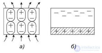
Fig. 8.21. Diagram of the electret polarization mechanism: а) — polarization of microdipoles; б) — injection of electric charge into the dielectric [48]
As a result, a spatially separated accumulation of charges of opposite sign (polarization) arises in the dielectric. To preserve the polarized state, the dielectric is cooled without switching off the electric field, as a result of which its polarized state is "frozen in." After such a processing cycle, the time during which the polarized state of the dielectric is retained increases by millions of times, which helps preserve the properties of the electret for many years [52].
Most often, for technical purposes electrets are used that are made in the form of thin nonpolar fluoropolymer films 10–25 µm thick, which may be coated on one side with a thin layer of metal, most often aluminum. The metal layer is deposited by vacuum evaporation. It serves as one of the electrodes of the device in which the electret is used. The electret is usually charged in a corona discharge from the free surface of the polymer side and carries excess charges of one sign in the dielectric (monoelectret). A charge of the opposite sign is induced and retained in the deposited metal layer.
Another type of electret — the photoelectret — is based on the action of an electric field and illumination of the dielectric surface. In the illuminated regions of a photosensitive dielectric, charge carriers are released as a result of the photoelectric effect; in the shadowed regions they settle as if in traps and form local charges. After the illumination is switched off, a charge distribution remains on the surface of the photoelectret, which represents a trace of the light's action, i.e., an image. Such an electrostatic image can be developed by depositing some coloring powder on the charged surface, whose particles are attracted to the charged regions of the photoelectret by electrostatic forces. Materials for photoelectrets include various salts, zinc oxide, zinc sulfides and selenides, and other substances. Fine polycrystals of sulfur, anthracene, naphthalene, and others can also be used in this class of dielectrics. An electrophotosensitive conducting plate is coated with a thin layer of photoelectret, pre-charged in the dark by a corona discharge. An image is projected onto the plate. Because of the high electrical resistance, the electret charge is retained for quite a long time. In the illuminated areas the charges relax, creating latent electrical images, which are then transferred to paper by means of pigment powders. This principle of image formation is widely used in copying devices and laser printers. A diagram of a laser printer is shown in Fig. 8.22.
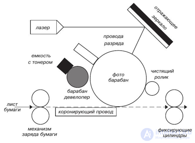
Fig. 8.22. Diagram used in laser printers to implement electrophotographic copying technology
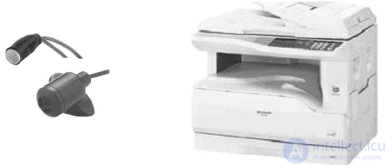
Fig. 8.23. Electret microphone and a copying machine (not to scale)
Electrets are widely used to create capacitors with controllable capacitance, microphones, pressure sensors, touch switches, and for recording signals and images. Fig. 8.23 shows the external appearance of compact microphones that use electrets as the input sensor, as well as a copying machine.
Electrets are used to create electric fields (electret lenses for focusing electrons, electret filters for cleaning flue gases, etc.) and to create transducers of mechanical displacements into electrical signals (electret microphones, electret keys, etc.). In addition, electrets are used in electrophotography, in dosimeters, and in vibration sensors. There are reports of the use of electrets in phonograph pickup heads and in low-power relays.
There are several traditional areas of application for electrets. They are used as elements of:
The first person to discover liquid crystals, or more precisely, the first to understand that this is an independent state of aggregation of matter, was the Austrian scientist Reinitzer. While studying a substance he had synthesized, cholesteryl benzoate, he found that when heated to 145° C the crystals of this substance melt, forming a turbid liquid that strongly scatters light. When a temperature of 179° C is reached, the liquid becomes transparent. The turbid phase of cholesteryl benzoate exhibited unexpected properties. Examining it under a polarizing microscope, Reinitzer discovered that it exhibits birefringence. The phenomenon of birefringence is a typically crystalline effect. This fact suggested that the liquid contains crystallites; however, studies by Lehmann showed that the turbid phase is uniform in composition and represents a new phase state. Lehmann called this state the liquid-crystalline state, or mesophase. "Mesos," translated from Greek, means intermediate, middle.
Liquid crystals are characterized by a strong dependence of optical properties, as well as a high sensitivity of optical properties to external electric and magnetic fields. These circumstances make it possible to use liquid crystals for manufacturing various indicators.
The term "liquid crystals" is usually used to refer to a large number of liquid-crystalline phases with different structures and properties.
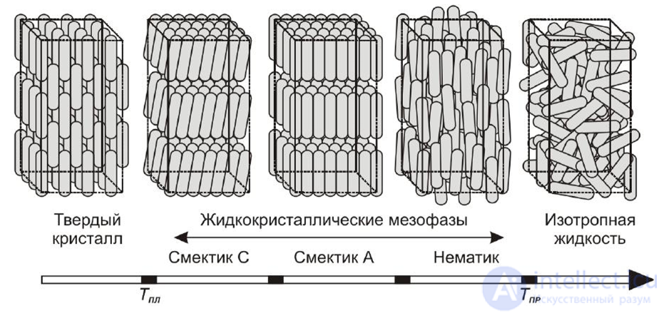
Fig. 2. Phase transitions in thermotropic LCs occurring on heating a sample
Nematics. This name comes from the Greek "nema" (nhma), meaning thread. The molecules of such substances are formations with a comparatively large molecular weight, and their extent in one direction is much greater than in the transverse directions. To characterize the orientational order of nematics, a unit-length vector is introduced – the director, whose direction coincides with the direction of the averaged orientation of the long axes of the molecules. In addition, another quantity is introduced, the order parameter S, which characterizes the degree of orientational ordering of the molecules.
 , ( 7)
where q is the angle between the direction of the director and the instantaneous direction of the long axis of a molecule.
Obviously, the parameter can take values from 0 to 1. The value S = 1 corresponds to complete orientational order, while S = 0 means complete orientational disorder and corresponds to a nematic that has transitioned into an isotropic liquid.
It is interesting that in the nematic state not all molecules have the same orientation. The requirement of maximum entropy of the system leads to the director being oriented differently in different regions. Therefore, regions with different director directions appear in the liquid crystal. Such regions, by analogy with ferroelectrics and ferromagnets, are called domains. At the boundaries between domains the refractive index of light changes, which is why liquid crystals appear turbid unless special measures are taken.
Smectics. The name comes from the Greek "smegma" (smhgma), meaning "soap." In these materials, besides the orientational ordering of the molecules, there is partial ordering of the centers of mass of the molecules. In other words, the centers of mass of the molecules are organized into layers, the distance between which is fixed. The layers of molecules easily slide relative to one another, and smectics feel soap-like to the touch. When such substances melt, a smectic phase forms first, then a nematic phase, and only at higher temperatures does a transition to an ordinary isotropic liquid occur. To describe smectics, a unit vector specifying the average orientation of the molecules – the director – and the order parameter S are used. Depending on the orientation of the director relative to the normal to the plane of the molecular layer, smectics with various structures are distinguished. The best studied are smectics with structure A and smectics with structure C. In smectics with structure A the director is directed perpendicular to the plane of the molecular layer.
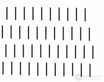
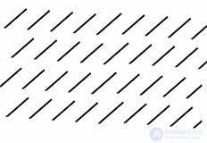
Figure 8 Molecular ordering in smectics with structures A and C.
In smectics with structure C, the director is not directed along the normal to the molecular layer but forms a certain angle with it. A schematic arrangement of molecules in smectics with structures A and C is shown in Figure 8.
Cholesterics. The structure of such liquid crystals resembles the structure of nematics. However, the directors of neighboring molecules are shifted relative to one another, as a result of which a cholesteric helix is formed. This phase behaves toward incident radiation like an interference filter. Since the pitch of the helix is on the order of 300 nm, white light is decomposed into a spectrum. In other words, if a flat layer of cholesteric liquid crystal is illuminated with white light, it will appear colored in reflected light, and the color will depend on the viewing angle and on the temperature. As the temperature changes, the pitch of the helix changes, which determines the effect of temperature on the color of cholesterics. Color thermal indicators are successfully used for technical and medical diagnostics. They make it possible to easily obtain a picture of a thermal field in the form of a color map. In addition, cholesterics can be used to visualize microwave fields.
Optical properties of nematics.
As noted earlier, the entire volume of a liquid crystal is broken up into domains, as a result of which optical inhomogeneity of the medium arises and strong scattering of light is observed. Such liquid crystals appear turbid. For practical use it is necessary to obtain a single-domain structure of the liquid crystal. In other words, it is necessary to use factors that stabilize the single-domain structure of the liquid crystal. Such factors can be:
Historically the first, but still relevant today, method of obtaining single-domain samples consists of special treatment of the surfaces bounding the liquid crystal. For surface treatment, scribing (making scratches), deposition of molecular layers onto the surface, and application of surface-active molecules of special substances – alignment agents – are used.
Uniformly oriented layers of nematic with the molecular axes parallel to the surfaces of the plates are called a planar texture, and those with axes perpendicular to the surfaces are called a homeotropic texture.
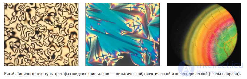
Obviously, the orienting influence of the surface on the liquid-crystal molecules is stronger the closer the molecules are to the surface. Therefore, one should expect that a homogeneous structure of the liquid crystal can be achieved in thin layers. Practice shows that complete structural homogeneity can be achieved by placing the liquid crystal between plates with a gap of 10–100 micrometers. The plates bounding the liquid crystal are usually made of transparent materials – glass or polymers; layers of tin oxide (SnO2) are used to make transparent electrodes.
Important characteristics of nematic liquid crystals are optical and dielectric anisotropy.
Optical anisotropy (Dn) is understood as the difference in the refractive indices of light waves whose electric vectors are parallel and perpendicular to the preferred orientation of the molecules. For typical cases Dn » 0.3, that is, uniformly oriented nematic structures behave like optically positive uniaxial crystals.
Dielectric anisotropy is understood as the difference in the values of the permittivity measured along and across the direction of the preferred orientation of the molecules (De). Depending on the sign of De, positive and negative dielectric anisotropy are distinguished. Positive dielectric anisotropy of a nematic corresponds to a lower permittivity (higher phase velocity) for light polarized perpendicular to the direction of the director. In a nematic with negative dielectric anisotropy, the phase velocity of light polarized perpendicular to the direction of the director turns out to be lower than the velocity of light polarized in the direction of the director.
The microscopic cause of the possibility of different signs of De lies in the structural features of the molecules forming the liquid crystal. The value of De is proportional to the order parameter S, that is, it changes with the temperature of the nematic, and its average value lies in the range 0.2–0.01 at an average permittivity of e = 2–2.5. The optical characteristics of a planar texture are such that only light linearly polarized orthogonal and parallel to the director propagates through it without a change in polarization. Any other polarization changes as the light propagates.
Let us prove this. Arbitrarily polarized light can be decomposed into waves polarized parallel and perpendicular to the director. Each of these waves travels at its own phase velocity, and a phase difference arises between the waves at the exit of the cell. Consequently, the sum of the emerging waves gives a wave with changed polarization.
Thus, the polarization properties of the planar and homeotropic textures of a nematic turn out to be different. Likewise, the properties of plates cut from ordinary crystals differ if they are cut so that in one of them the optical axis is perpendicular to the surface, and in the other parallel to it. An essential difference between nematics and ordinary crystals is that in nematics the direction of the optical axis can be changed by external actions. Thus, when an electric field is applied, the molecules of the nematic orient themselves so that the direction of the larger value of the permittivity coincides with the direction of the field. In this way, a cell with a homeotropic structure can be converted into a cell with a planar structure. By placing a polaroid film on the cell, the transparency of the cell can be changed by applying a voltage. Calculations performed by Fredericks and coworkers showed that voltages on the order of a few volts are needed to restructure a typical cell. The restructuring time of the cell is on the order of a millisecond.
Electro-optical effects in the cell can appear not only as transitions from a transparent to an opaque state or vice versa, but also as a change in the color of the cell. If a small amount of a dichroic dye is added to the nematic, then when the nematic molecules are reoriented, the dye molecules are reoriented as well, which leads to a change in the color of the cell.
In terms of their electrical properties, liquid crystals belong to the class of polar dielectrics with relatively low resistivity (r=106-1010 Ω·m). When operating in constant fields, the movement of ions and their interaction with the electrode material leads to gradual degradation of the cells – loss of contrast. In addition, in materials with low resistivity, the flow of ions disrupts the ordered arrangement of the nematic molecules. As a result, scattering regions form, which manifests itself as clouding of the cell. This effect is called dynamic light scattering.
The dynamic scattering effect of light is also used to make indicators. The advantages of such indicators are that, under alternating voltage, electrolysis processes can be weakened and the service life of the indicators extended to tens of thousands of hours. In addition, the effect appears in unpolarized light, which simplifies the design of the indicators. The drawback is the need to use higher voltages than in the case of purely field effects.
Since liquid-crystal indicators use ambient light, the power consumption is much lower than that of other indicator devices, amounting to 10-4 – 10-6 W/cm2. This is several orders of magnitude lower than in LEDs, powder and film phosphors, and gas-discharge indicators.
Other advantages of liquid-crystal indicators are:
The fundamental drawbacks of liquid-crystal devices are their low speed of response, as well as their susceptibility to electrochemical and photochemical aging processes.
Optical properties of cholesterics
When a cholesteric is placed in an electric or magnetic field, distortion of the molecule's helical pitch occurs. In sufficiently strong fields, with positive dielectric or magnetic anisotropy, the cholesteric helix unwinds completely. This behavior of the helix in an external field is related to the competition between the intermolecular interaction, which tends to establish helicoidal ordering of the long axes of the molecules, and the interaction of the molecules with the applied field, which orients the long axes of the molecules along the field. A change in the helical pitch under an external field causes a change in the color of the cholesteric and can be used to create color indicators. It should be noted that applying a field to a planar structure is technically inconvenient, so applying the field perpendicular to the surface of the cells is of greatest interest. If a field perpendicular to the surface of the cells is applied to a cholesteric with negative dielectric anisotropy, it has a stabilizing effect on the planar texture. In addition, the helical pitch decreases, which makes it possible to control the color of the cell.
As in nematics, in cholesterics hydrodynamic effects appear upon application of a sufficiently strong electric field. In other words, turbulent flows appear in the cholesteric, and the cholesteric ceases to be transparent. That is, dynamic light scattering appears in the cholesteric.
Unlike in a nematic, dynamic light scattering in a cholesteric can exhibit memory. The light-scattering state can persist even after the field is removed. The memory time depends on the specific properties of the cholesteric and can range from minutes to several years. Applying an alternating voltage returns the cholesteric to its initial non-scattering state. This property makes it possible to use cholesterics to create memory cells.
Optical properties of smectics.
Smectics are the most extensive class of liquid crystals. Moreover, some varieties of smectics possess ferroelectric properties.
Smectic A is an optically uniaxial medium, since the optical axis coincides with the direction of the director, for which the refractive index does not depend on the polarization of light. Smectic C is a
продолжение следует...
Часть 1 4.14. Classification of Active Dielectrics: Ferroelectrics, Piezoelectrics, Pyroelectrics, Electrets
Часть 2 Superionic conductors. - 4.14. Classification of Active Dielectrics: Ferroelectrics, Piezoelectrics,

Comments