Lecture
The case of the bulk stress state is shown in Fig. 9.2. As already noted in section 9.1 of this manual, normal stress acts on each face 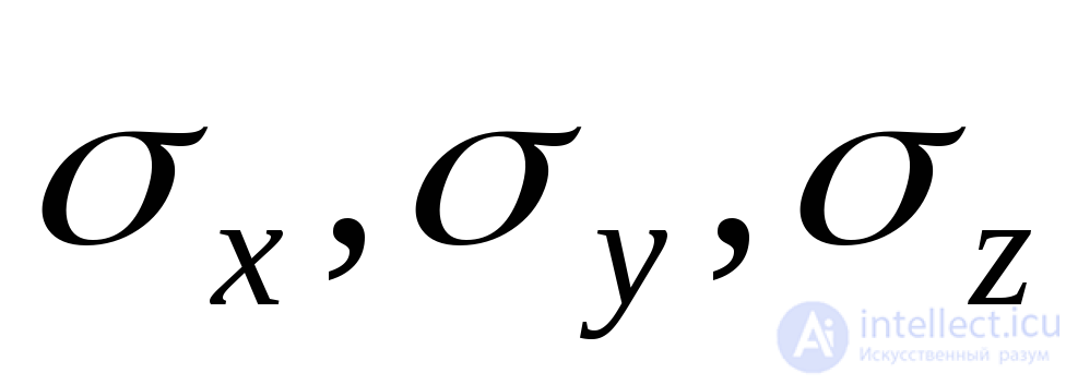 , as well as two components of the shear stress
  .
.
Thus, the stress state in the selected elementary parallelepiped is generally characterized by nine stress components, which can be written in the form of a stress tensor:
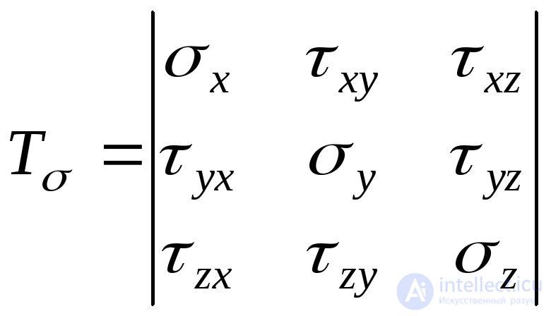 . (9.25)
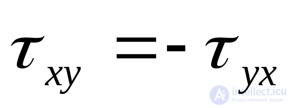
The tangential stresses represented by the stress tensor are connected by a number of dependencies, which can be obtained by composing the equation of the sum of the moments of all forces relative to the coordinate axes 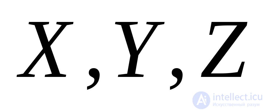 (Fig. 9.2):
 ;
; 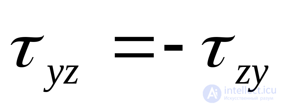 ;
; 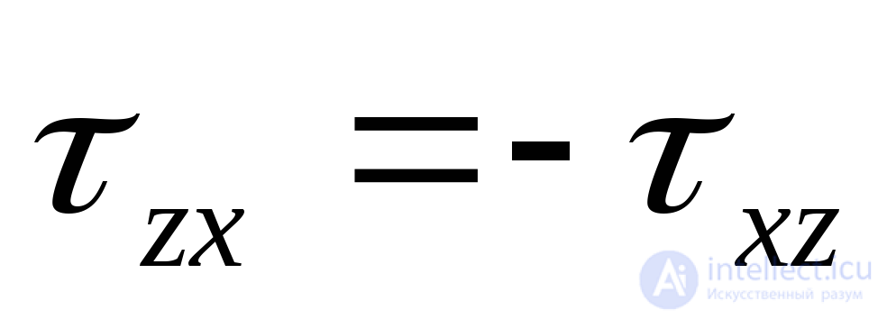 . (9.26)
The modules of these stresses are the same, and the signs are opposite on the basis of the law of paired tangential stresses (9.8).
The general case of a stress state (Fig. 9.19a) can be represented as the sum of two stress states, characterized in the first case by the same normal stresses 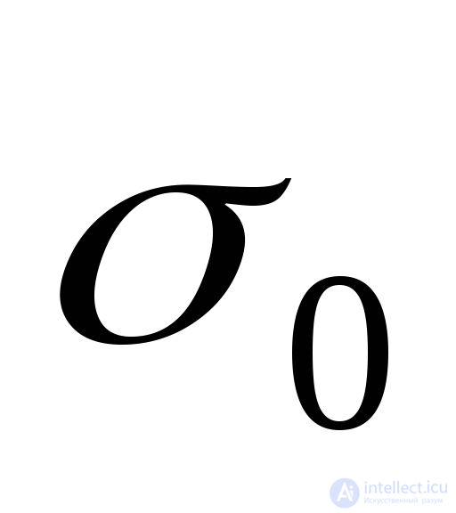 (Fig. 9.19, b) and in the second case (Fig. 9.19, c) - normal voltages:
 ;
;  ;
;  (9.27)
and shear stresses  .
.
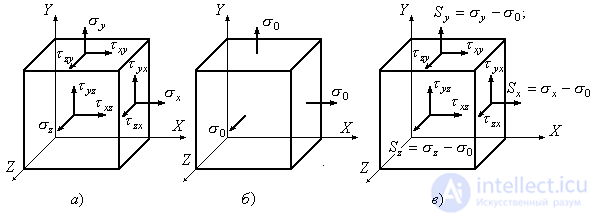
Fig. 9.19
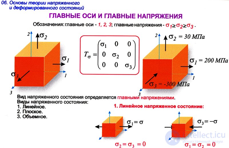
We accept:
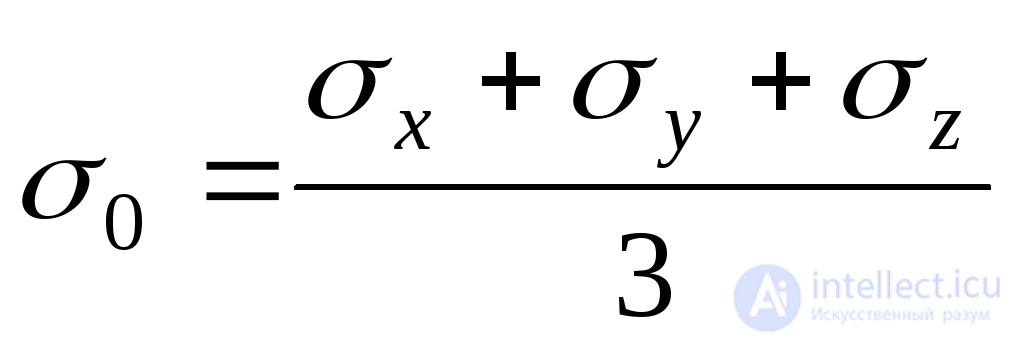 . (9.28)
Then from (9.27) it follows:
 . (9.29)
The stress state shown in Fig. 9.19, b can be described by the spherical stress tensor:
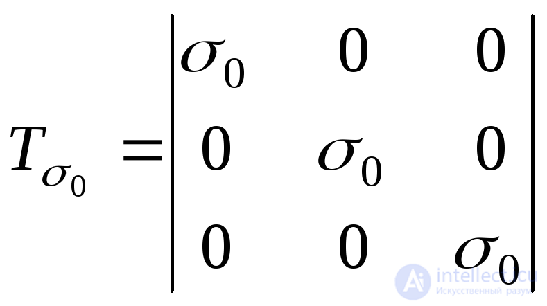 . (9.30)
The stress state shown in Fig. 9.19, c, can be described by a tensor, which is called the voltage deviator:
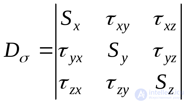 . (9.31)
The ball tensor characterizes the change in the volume of the selected element, the deviator characterizes the change in the shape of the element.
Consider the definition of principal stresses 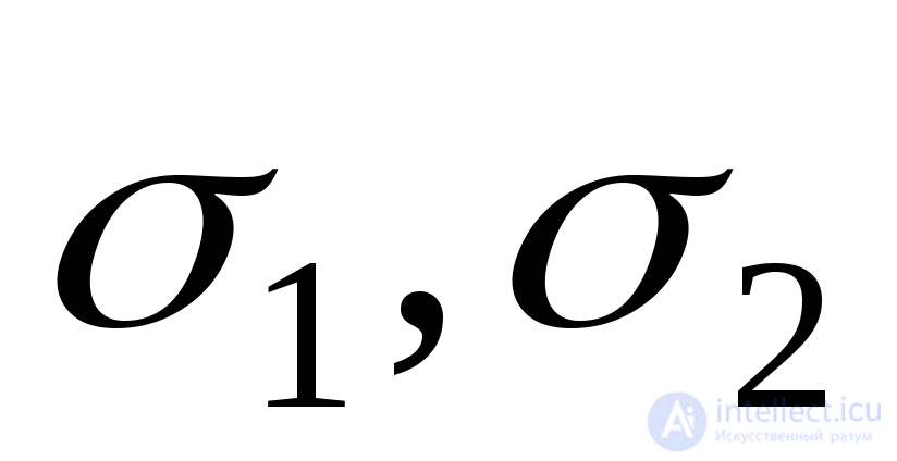 and
and 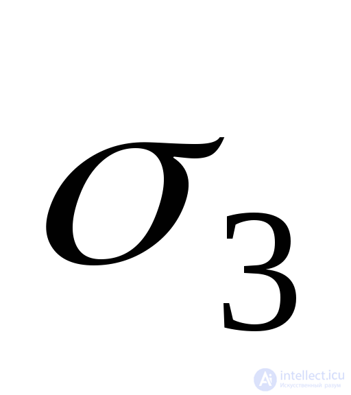 , through the stresses acting on arbitrary sites (Fig. 9.19, a). Suppose that we know the position of the main site, determined by the slope of the normal to this site
  in relation to the coordinate axes
 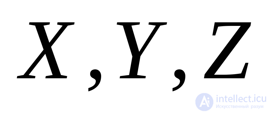 . With a section parallel to this site, we select the tetrahedron shown in Fig. 9.20 from the initial parallelepiped and compose the equilibrium conditions of the tetrahedron in the form of sums of projections of all the acting forces on the coordinate axis.
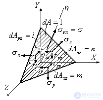
Figure 9.20
The cosines of the angles formed by the normal  with coordinate axes
 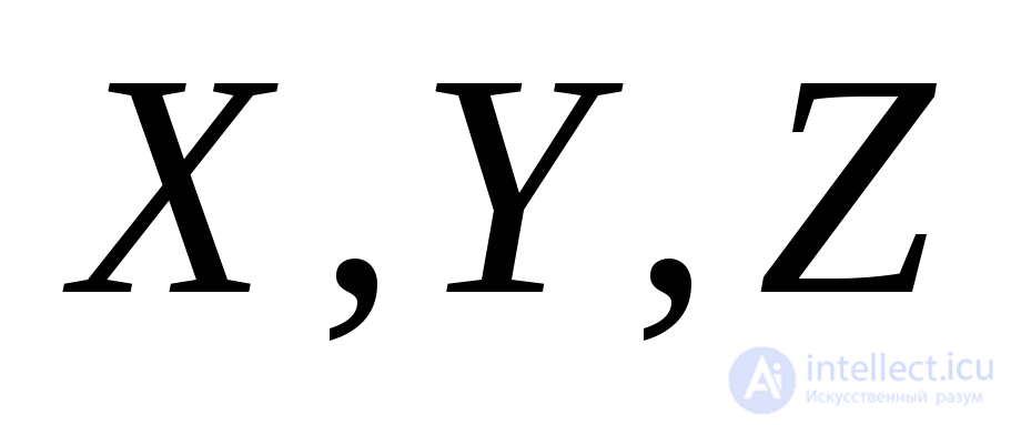 , denote respectively
 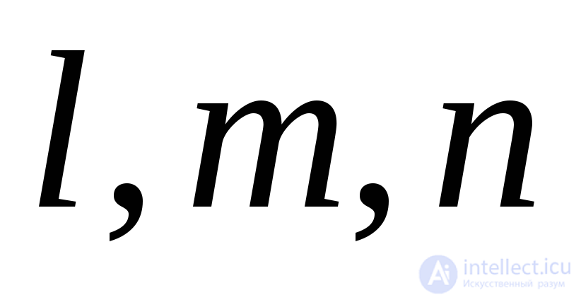 . We take the area of the inclined face
  , then the areas of other faces lying in the coordinate planes will be
 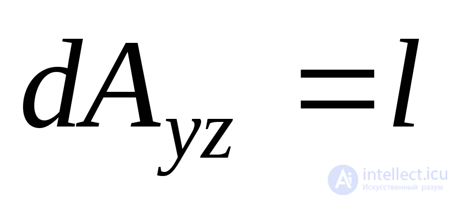 ,
, 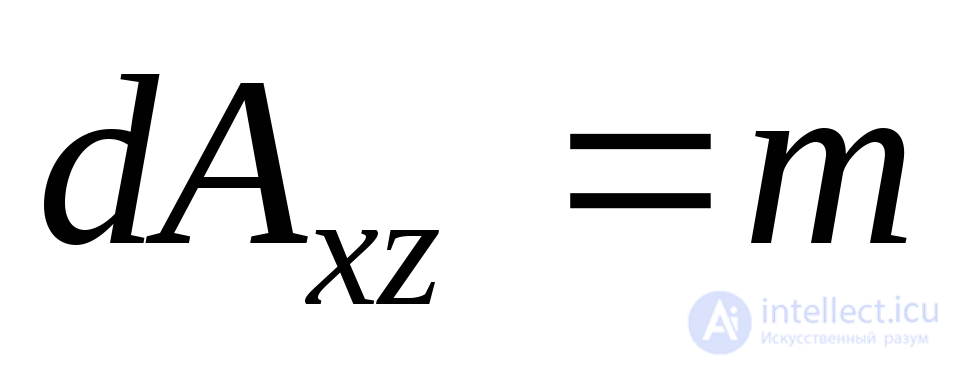 ,
, 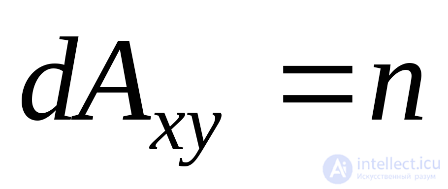 . There are no tangential stresses at the main site. The main voltage acting here
 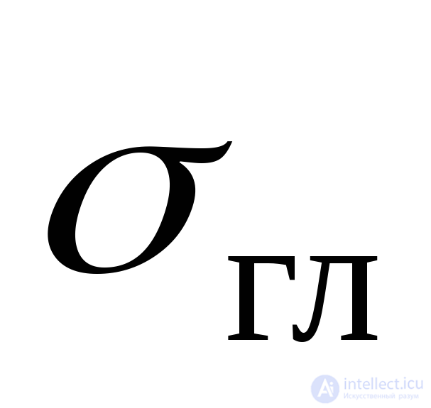 denote
 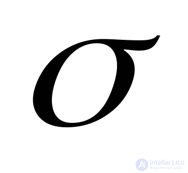 . The sum of the projections of the forces on the axis
  gives:
 .
.
Projecting all the forces on the axis 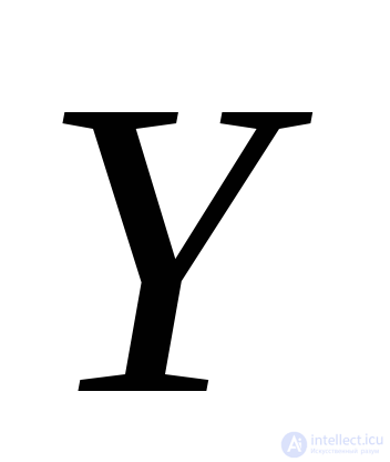 and
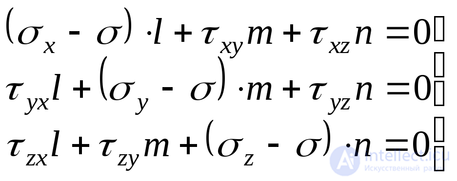
and  , we get two more similar equations. Thus, we will have the following three equilibrium equations for the tetrahedron:
 . (9.32)
Equations (9.32) can be considered as a homogeneous system of equations with respect to unknowns 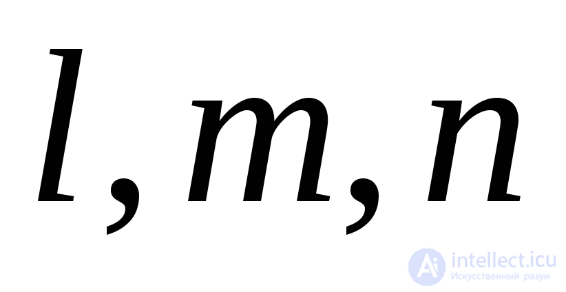 . Between Guide Normal Cosines
  there is a dependency
 , (9.33)
therefore, they cannot simultaneously equal zero. It is known that under this condition the determinant of system (9.32) must be equal to zero, i.e.
 . (9.34)
Having opened the determinant (9.43), we arrive at the cubic equation:
 , (9.35)
whose three roots represent the main stress 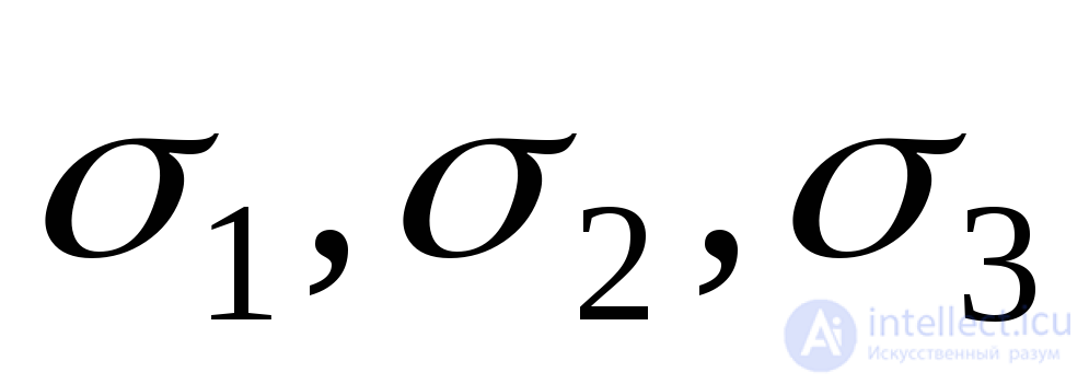 .
.
The coefficients of equation (9.35) take the form:
 ; (9.36)
 ; (9.37)
 . (9.38)
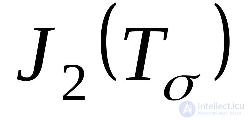
Since the principal stresses are independent of the choice of coordinate axes, the cubic uranium coefficients (9.35) also do not change when the coordinate axes are rotated, i.e. are invariants and are called, respectively, the first 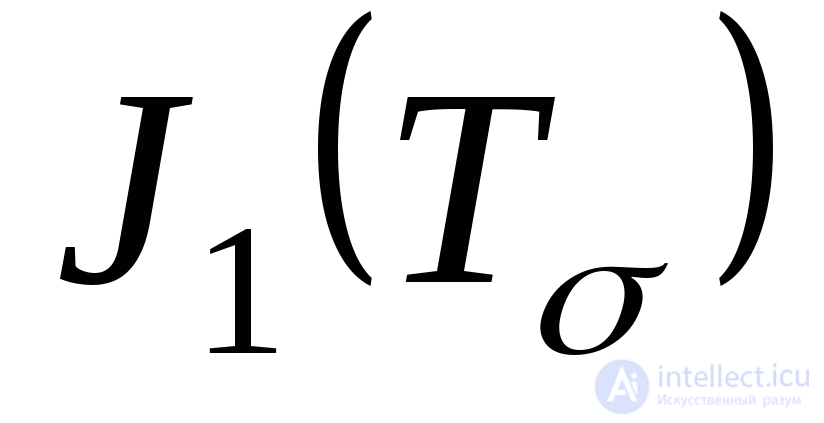 second
  and third
 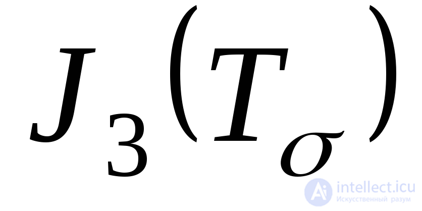 invariants of the stress tensor. From formulas (9.36) - (9.38) it follows that the expressions of the invariants of the stress tensor in terms of the principal stresses have the form:
 ; (9.39)
 ; (9.40)
 . (9.41)
In the particular case of a plane stress state, the cubic equation (9.35) reduces to a square one, whose two roots give values 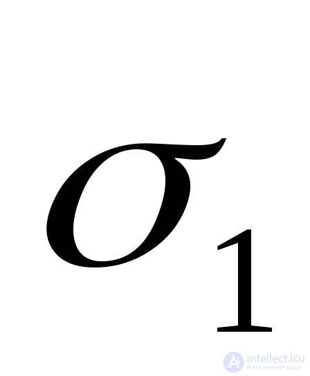 and
and 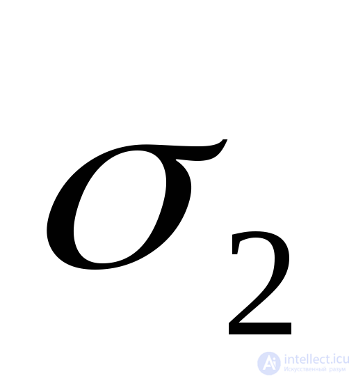 coinciding with formulas (9.19) obtained above. In this case, you need to put
  since the face
  the source box must be free of stress.
To determine the guide cosines 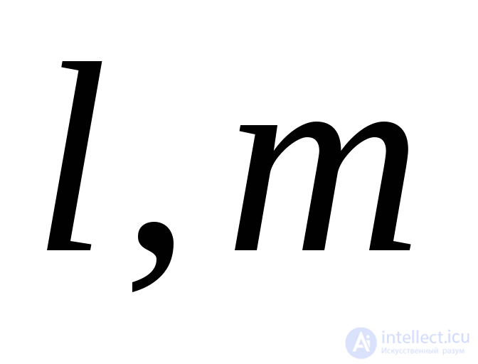 and
and  corresponding to one of the three main stresses
 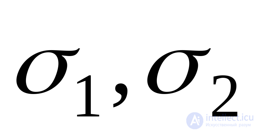 and
and 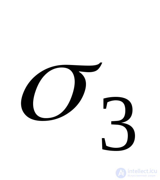 , you need to substitute the value of this main voltage into expression (9.32) instead
 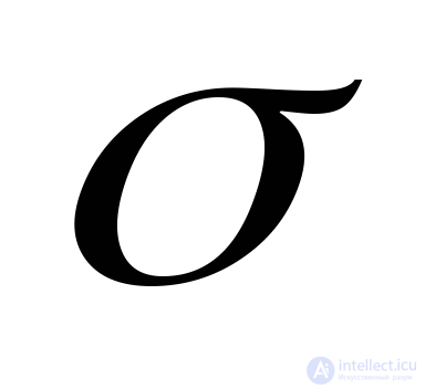 . The joint solution of equations (9.32) will give the desired quantities
 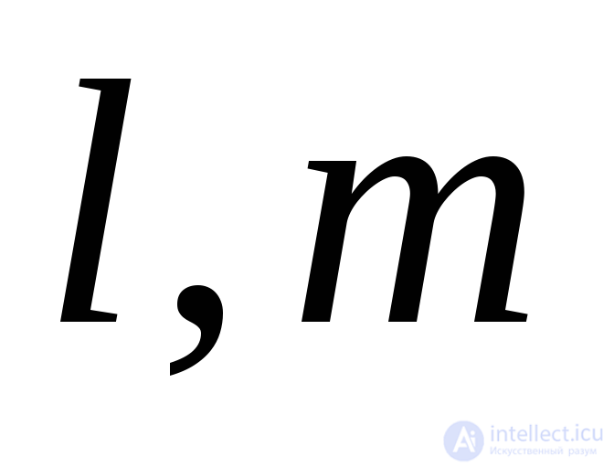 and
and  .
.
To determine the maximum tangential stresses, we assume that the principal stresses 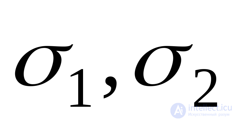 and
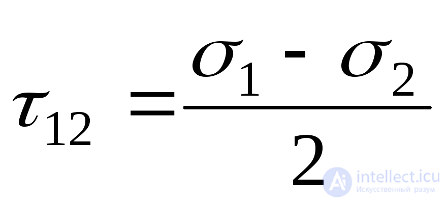
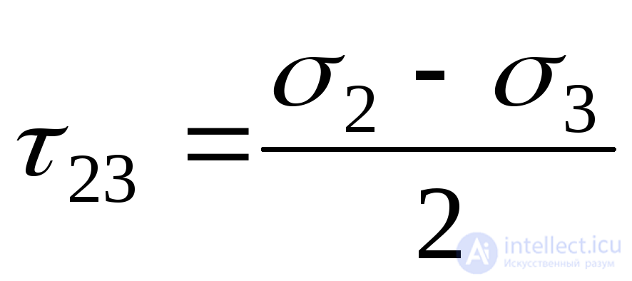
and 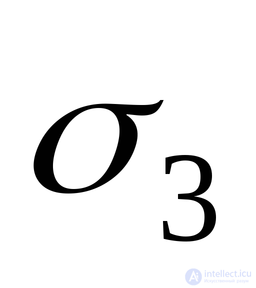 known . As in the case of a plane stress state, the maximum tangential stresses act in areas tilted at an angle of 45 ° to the main stresses. The tangential stresses at these sites will be:
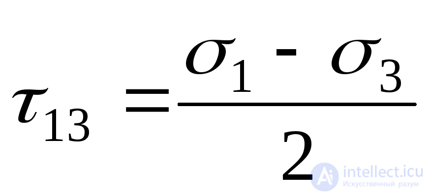 ;
;  ;
;  . (9.42)
The largest of these stresses determines the maximum tangential stresses at a point:
 . (9.43)
Thus, in the general case, the maximum tangential stress at a point acts on a site inclined at an angle of 45 0 to the maximum and minimum of the three principal stresses, and is equal to their half-difference.
The strength of the material or its transition under load into a plastic state in some cases is associated with the value of the maximum tangential stress 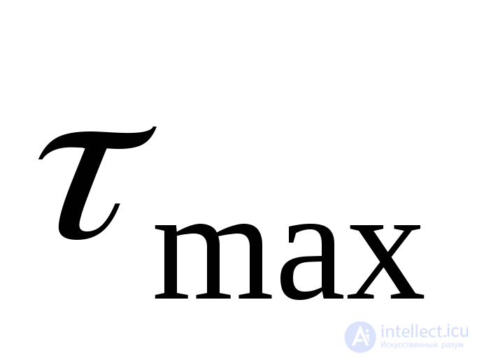 , and therefore it, along with the main stresses, is an important characteristic of the stress state.
We obtain formulas for stresses 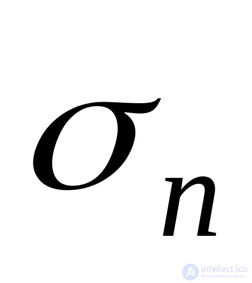 and
and 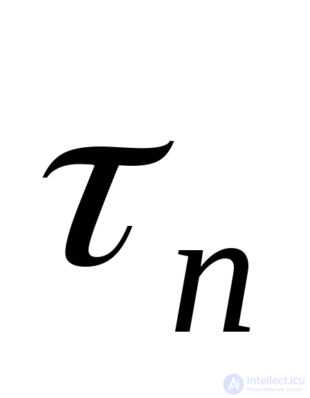 acting on an arbitrarily oriented platform, the position of this site is determined by the angles
 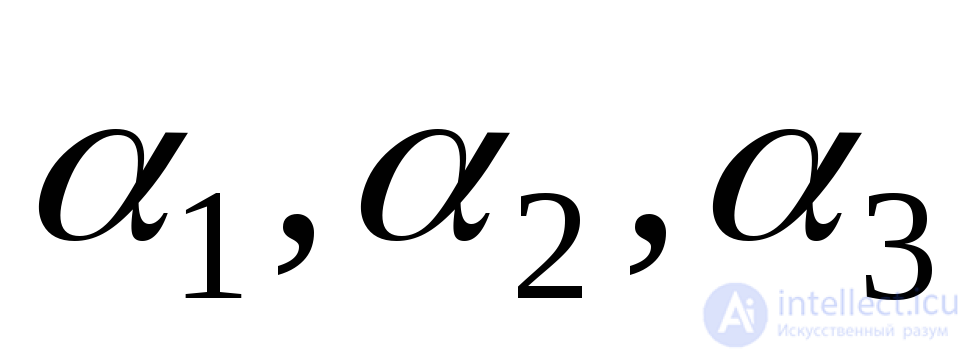 formed by the normal
  to this site with axes 1, 2 and 3, respectively parallel to the main stresses
 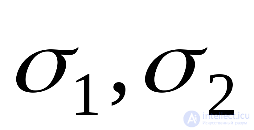 and
and 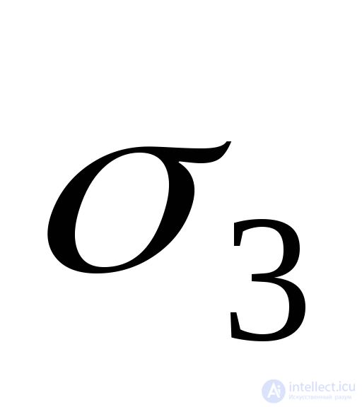 . Stress formulas
 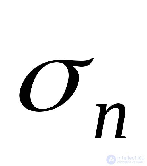 and
and 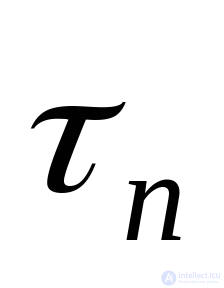 we obtain from the equilibrium condition of the elementary tetrahedron (tetrahedron) shown in Fig. 9.21, selected from the main parallelepiped.
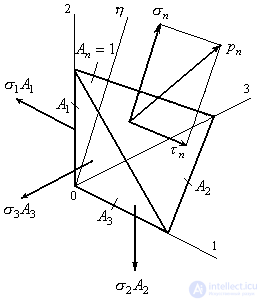
Figure 9.21
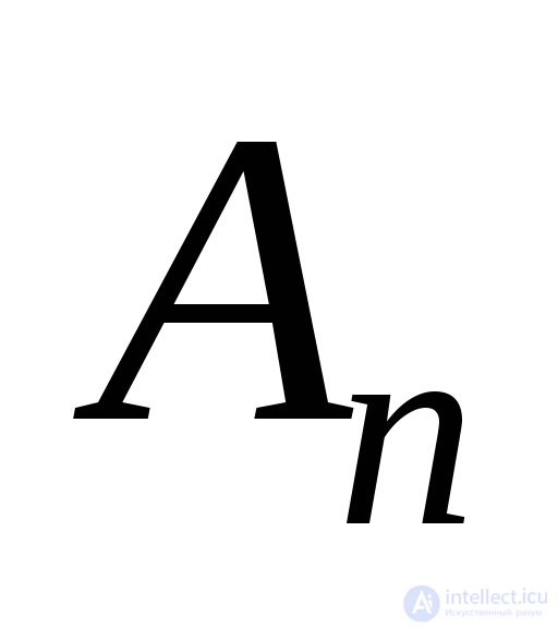
Take the area 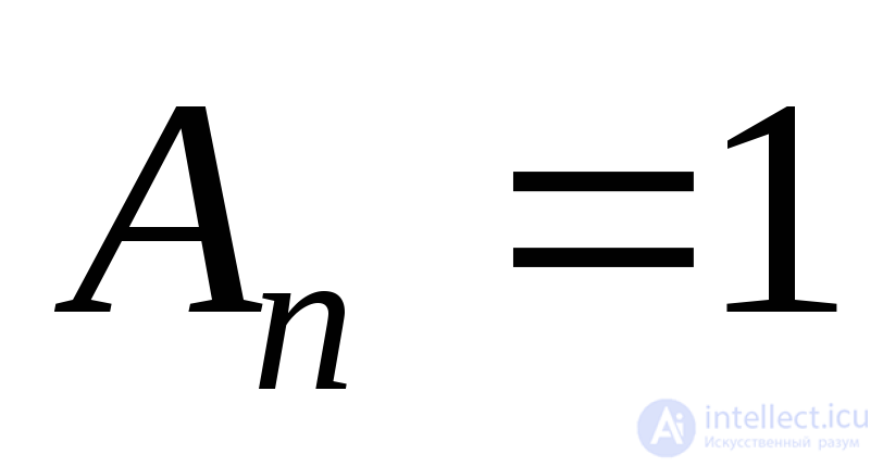 then the areas of the other faces of the tetrahedron as projections
  on the coordinate planes will take the form:
 ;
;  ;
;  . (9.44)
Projecting all forces to normal  we find
 , (9.45)
whence, given (9.44), we obtain the formula for the normal voltage:
 . (9.46)
Since we do not know the direction of shear stress 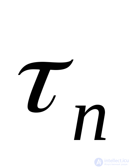 , then first we find the total voltage
 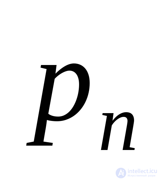 .
.
If in space we construct a polygon of forces acting on a tetrahedron, then the vector 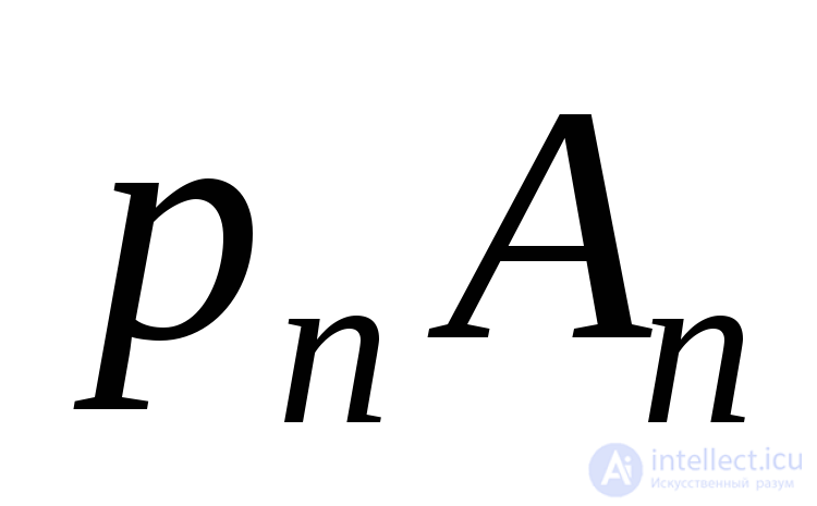 will be the diagonal of the parallelepiped whose edges are equal
  . Thus:
 .
.
From here, using (9.44), we obtain the total voltage:
 . (9.47)
Now you can determine the shear stress:
 . (9.48)
Formulas (9.46) - (9.48) show that the three main stresses 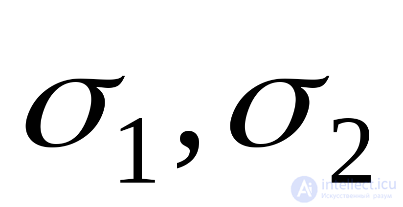 and
and 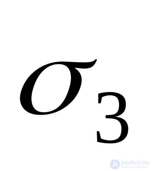 completely determine the volumetric stress state.
The area equidistant to the direction of the three main stresses is called octahedral , and the stresses acting on it are called octahedral stresses . The indicated sites cut off equal segments on the axes 1,2 and 3 and form an octahedron - octahedron in space (Fig. 9.22).
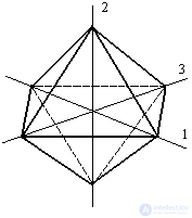
Figure 9.22
Cosines of angles 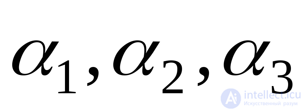 are the guide cosines for the normal
  and therefore are related by:
 .
.
For octahedral sites  and therefore
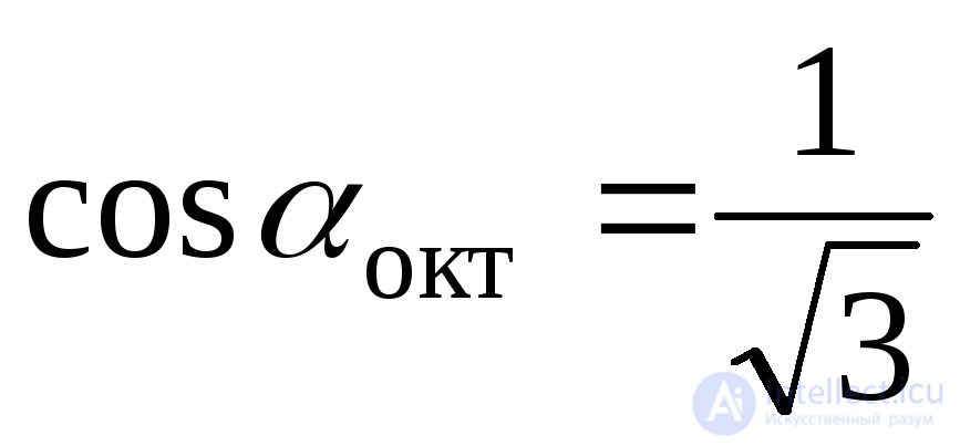 .
.
Substituting this value of cosines in (9.46) and (9.47), we find:
 . (9.49)
 . (9.50)
By the formula (9.48)

 .
.
From here we finally have:
 . (9.51)
When studying the issues of body strength, the general deformation of a material in the vicinity of a point is divided into deformations of changes in volume and shape. The importance of octahedral stresses is determined by the fact that stress is associated with the first of these deformations. 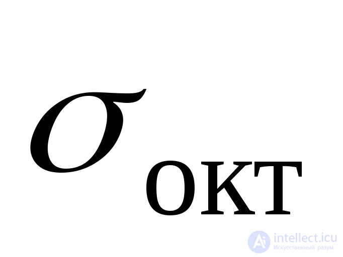 and from the second
 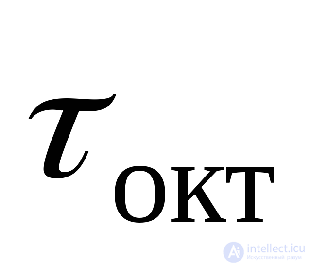 .
.
Knowing the tangent octahedral stresses, we can calculate the stress intensity :
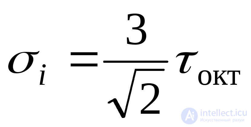 (9.52)
or
 (9.53)
Comments
To leave a comment
Strength of materials
Terms: Strength of materials