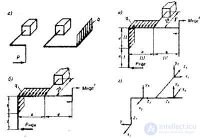
| In a spatial frame, in contrast to a flat one, both the rods that make up the frame and the loads are not in the same plane (Fig. 7.4 a, 6). In constructing plots, the truncation method is used, as in other cases. In the presence of a seal, it is convenient to bypass the frame from the free end, otherwise with a general load, six reactions must be defined in the seal — three forces and three points. |
- A sliding system is used. The coordinates, while the Z axis is always directed along the rods. The x, y, z axes are rigidly interconnected and rotate with the z axis (Fig. 7.4 c, d).
- The sums of the projections of the external forces acting on the left part of the frame, on the longitudinal axes of the rods, are equal to the longitudinal forces Ni, on the transverse axes to the transverse vultures Qi.
- The rule of signs for the longitudinal force N is the same; the sign of the transverse force Q is not determined. The sign of the bending moment is also not definable, the plot is built on compressed fiber.
- Ni plots are constructed in any plane on either side of the rods. Plots Q are convenient to build in the plane of action of force, which causes a transverse force Q.
- On mutually perpendicular rods lying in the same plane, when there is a load perpendicular to the plane of the rods, the bending moments become twisting and vice versa.
- External forces load all the rods that connect the point of application of force with the seal.
- When constructing plots in spatial frames, it is convenient to consider each core separately, ie:
- a) fasten the rods (put a seal) at the points of connection with adjacent rods;
- b) load the rods at the beginning with all the efforts that come from neighboring rods;
- c) build on this rod the diagrams of each force factor (Fig. 7.4, a, b, c, d), which came to the beginning of the plot, separately;
- d) determine the direction of the bending moments from the Mizg plots, remembering that they have been compressed on compressed fibers.
|

Comments
To leave a comment
Strength of materials
Terms: Strength of materials