Lecture
| Example 1 |
| For a beam, clamped at one end and loaded at the free end by force P, determine the deflections of the free end (fig. 6.4) and the cross section k (fig. 6.5). |
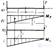 |
| Fig. 6.4 |
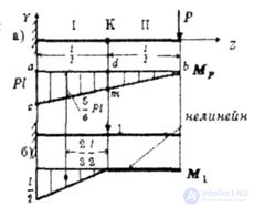 |
| Fig. 6.5 |
| Decision. |
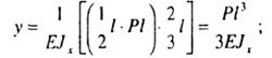
| Define the deflection of the free end. |
|
 |
|
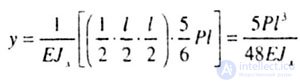
| Now we define the deflection of the cross section K. The curve of the bending moment from force P (Fig. 6.5, a) remains the same and will be linear throughout the beam, and the plot from the unit force applied in cross section K (Fig. 6.5, b) is broken therefore, applying the rule of Vereshchagin, we take the area of the plot M 1 , and the ordinate on the plot M p . |
 |
| Example 2 |
| Determine the angle of rotation of the point C of the beam, clamped by the left end and loaded with a uniformly distributed load q (Fig. 6.6). |
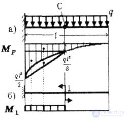 |
| Fig. 6.6 |
| Decision. |
|
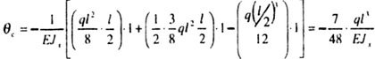 |
| Example 3 |
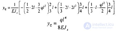
| For a given beam with a continuous uniformly distributed load with intensity q, determine the deflection in the cross section C. (Fig. 6.7). |
| In many cases, it is convenient to build a cargo plot in the so-called “stratified” form: a series of independent diagrams are constructed for each load. The essence of the stratification of the diagram will be shown on a specific example (Fig. 6.7.). |
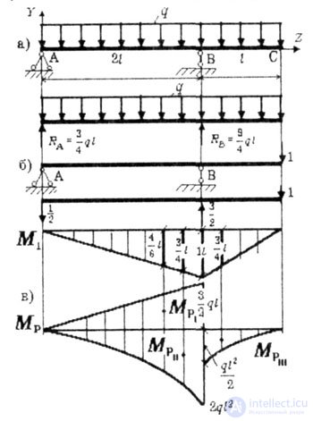 |
| Fig. 6.7 |
| Decision. |
|
 |
|
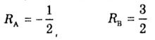 |
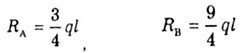
| and build a plot of M 1 (Fig. 6.7, b). A single plot has a break in the TV Therefore, stratification of the cargo epure is conveniently carried out with respect to section B, approaching it from two sides (Fig. 6.7, c). On the left we plot the diagrams of the reaction R A , the distributed load q; to the right of the distributed load q. |
|
 |
| We can recommend another method of multiplying plots. |
| It is possible to multiply the diagrams, having the form of a trapezoid, “twisted” trapezium, or when one of the diagrams is outlined in a square parabola, using ready-made formulas. There is no need to find the position of the center of gravity of the area of one of them (Fig. 6.8). |
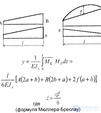 |
| Fig. 6.8 |
| If two rectilinear diagrams are multiplied (two trapeziums), then only two terms are preserved in the last formula. |
| This method is good for machine counting. |
| Note. |
| The latter formula is also applicable when one or both of the plotted diagrams have the form of a triangle. In these cases, the triangle is considered as a trapezoid with one extreme ordinate equal to zero. |
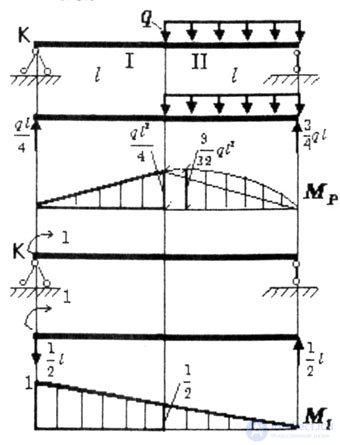
| Example 4 |
| Determine the angle of rotation of the section K of the beam (Fig. 6.9). |
 |
| Fig. 6.9 |
| parabolic triangle with height. |
| Decision: |
| 1st method. |
| As in the previous tasks, we plot the plot M p and M 1 . Plot M p consists of an isosceles triangle with height |
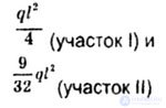 |
| We use the Mueller-Breslau formula |
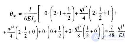 |
| 2nd way. |
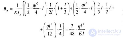 |
| The answers matched. |

Comments
To leave a comment
Strength of materials
Terms: Strength of materials