Lecture
| In cases of tension-compression (a) or torsion (b) the ordinates of the plot of the longitudinal forces or torques also show their values in the corresponding cross-sections (Fig.1.11a.b). |
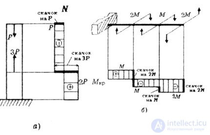 |
| Fig. 1.11 |
| Any internal force is determined by external loads using the section method. |
| Each plot on their sites has signs. |
| The rules of signs for internal efforts applied in mechanical engineering. |
|
| It is usually agreed that when looking at the normal to the cut-off part, the internal torque is considered positive if it turns the cut-off part clockwise. |
When bending between the transverse force Q, the bending moment M, the angle of rotation of the cross section  and deflection Y there are differential dependences, allowing to establish the following characteristic features of plots: and deflection Y there are differential dependences, allowing to establish the following characteristic features of plots: |
|
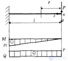 |
| Fig. 1.12 |
| M = - P * z - equation of a line. |
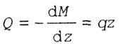
| In accordance with the differential dependence of Zhuravsky: |
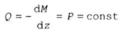 |
| From this it follows that on a straight line, not loaded by an external flight load, the section of the rod of moments M is rectilinear, and the diagram of shear forces Q is constant (Figure 1.12). |
|
|
|
|
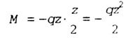 |
| square parabola equation. |
| In accordance with the differential dependence of Zhuravsky: |
 |
| straight line equation. |
| Thus, in the section with a distributed load, the diagrams of the bending moments M are outlined along a square parabola with a bulge in opposition to the action of the distributed load, and the diagram of transverse forces Q has the form of a trapezoid or treugopnik. It is outlined with a straight, oblique line AB, with the direction of inclination (when going from left to right) coinciding with direction q (Fig. 1.13 a, b, c). |
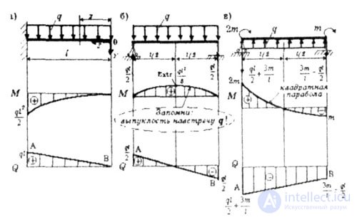 |
| Fig. 1.13 |

Comments
To leave a comment
Strength of materials
Terms: Strength of materials