Lecture
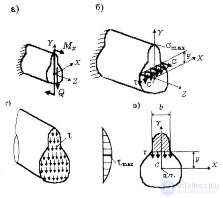
| At all points of the timber cross section, normal and tangential stresses occur during lateral bending (in Fig. 5.1.6, these stresses are shown at points at a distance of Y from the X axis): |
 |
| Fig. 5.1 |
| Legend. |
| M x , Q - internal forces: bending moment and shear force, they vary along the beam and are determined by plotting; |
| y is the coordinate of the cross-section points at which stresses are determined; |
| b is the width of the cross section at the point where shear stresses are determined; |
| J x - the main central moment of inertia is the moment of inertia about the central axis x, |
| с x * is the static moment relative to the neutral axis z of that part of the cross-sectional area, which is located above (or below) the longitudinal section — above or below the level y, at the points of which the tangential stresses are determined. |
 |
| These formulas are derived in the main central axes of the beam cross section. In fig. 5.1 is the X, Y axes. The Y axis coincides with the axis of symmetry of the section, and the X axis, perpendicular to the bend plane, passes through the center of gravity of the section and is the neutral axis: the normal stresses at the points of this axis are zero. Z axis - the axis of the beam. |
| Thus, at the level of voltage, defined by the above formulas, are constant, do not depend on the coordinate X. |
| With an increase in the coordinate y, the normal stresses increase and at the points farthest from the neutral axis reach the highest value: |
 |
| For calculations, a special geometrical characteristic is used - the moment of section resistance during bending: |
 |
| The tangential stresses, on the contrary, decrease and in the most distant from the neutral axis the points vanish, and the regions of the neutral axis reach the highest values (Fig. 5.1, d). In addition, the highest values of tangential stresses are significantly less than the maximum values of normal stresses: so for a cantilever rod of rectangular cross section loaded with a concentrated force at the free end, the ratio of the maximum values of these stresses |
 |
| where l, h is the length of the timber and the height of its cross section. |
| Therefore, when l >> h, which takes place in most cases, shear stresses are negligible compared to normal ones and are not taken into account in strength calculations. |
| The strength condition is as follows: |
 |
 - allowable stress. - allowable stress. |
| The process of calculating the beam strength should be conducted in a certain sequence. It is necessary: |
|
| Then, at each site, an arbitrary section is selected, for which expressions are drawn up to determine the internal efforts, which are used to plot the graphs of these efforts. |
| The diagrams of the internal forces determine the dangerous sections in which these efforts reach the highest values. |
| In most cases, the main internal force in the calculation of the beam strength is the bending moment and the associated normal stresses. |
|
| After determining the position of the dangerous sections with the largest values of bending moments, in these sections the highest normal stresses are calculated: |
|
These stresses are compared with the allowable voltage.  : : |
 |
| after which a conclusion is made about the strength of the timber. |
|
 |
| the question of the strength of the timber. |
Comments
To leave a comment
Strength of materials
Terms: Strength of materials