Lecture
The most common in problems of resistance of materials is a plane stress state: during torsion, bending, bending with torsion, etc. Let us dwell on it in more detail.
Select the box from the body (Fig. 9.8). Under the action of forces applied to its faces, the parallelepiped is in equilibrium. The lengths of the edges of the parallelepiped are assumed to be infinitesimal and equal  .
.
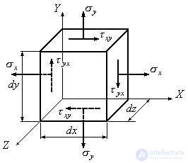
Figure 9.8
Consider inclined platforms perpendicular to the unloaded parallelepiped faces. We cut the elementary parallelepiped, shown in Fig. 9.8, with an oblique section perpendicular to the plane  , selecting an elementary triangular prism from it (Fig. 9.9a).
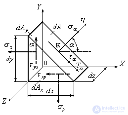
Figure 9.9
The slope of the site with the desired stress will be determined by the angle  which forms the external normal to this site with the axis
  . From figure 9.9 it follows that
 (9.6)
(9.6)
The system of forces shown in Fig.9.9 is a plane arbitrary system. The equilibrium of such a system of forces is described by three independent equations. Compose these equations.
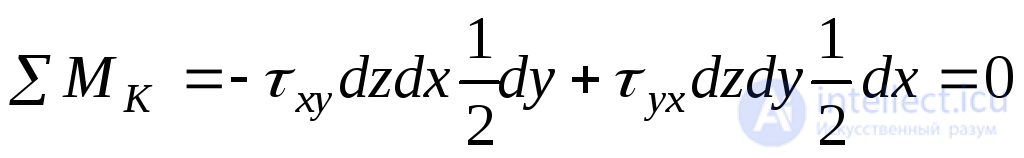 . (9.7)
From:
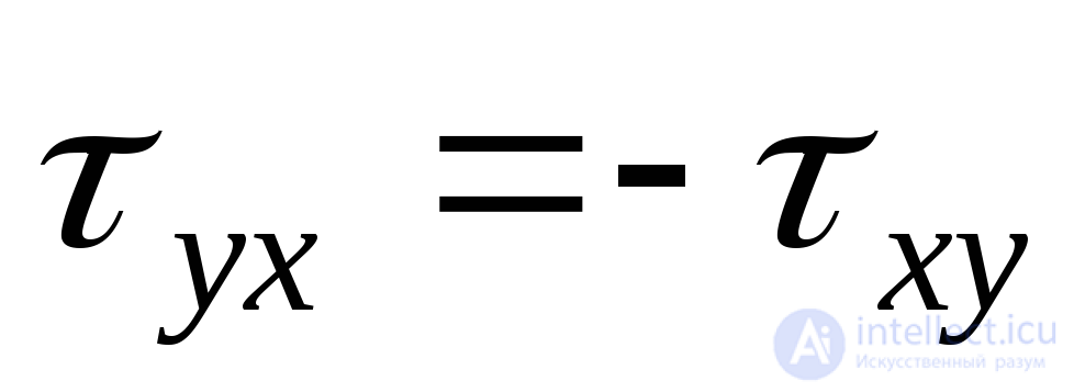 . (9.8)
Expression (9.8) is the law of paired tangential stresses: tangential stresses acting on any two mutually perpendicular sites are equal in magnitude and opposite in sign .
In the case of a plane stress state, only two variants of the action of shear stresses are possible (Fig. 9.10).
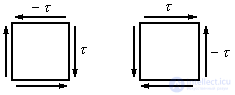
Figure 9.10
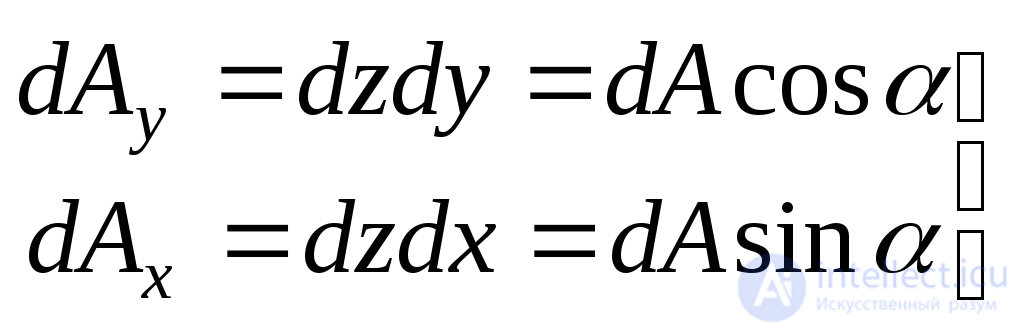
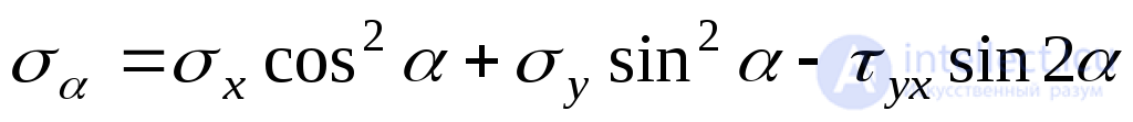
To determine the stresses on an inclined platform, we design the forces acting on the prism (Fig. 9.9) on the axis  and
and  . We get:
 ; (9.9)
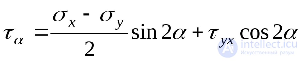
 . (9.10)
Substituting in (9.9) - (9.10) instead  and
and  from expression (9.6), we reduce all terms to
  . Further, given that according to (9.8)
  , but
, but  and
and  we find:
 ; (9.11)
 . (9.12)
We represent formula (9.9) in a slightly different form, using the equalities known from trigonometry:
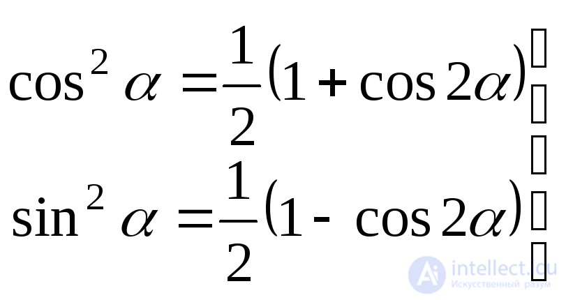 . (9.13)
Substituting (9.13) into (9.11), we obtain:
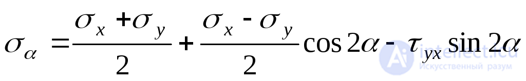 . (9.14)
Find out the relationship between normal voltages  and
and  acting on two mutually perpendicular sites (Fig. 9.11).
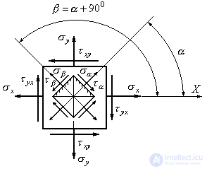
Fig. 9.11
Voltage  is determined by the formula (9.14). Voltage
  we get if we substitute in this formula
  :
:
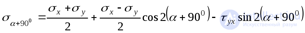
or
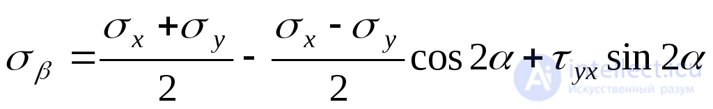 . (9.15)
Adding (9.14) and (9.15), we conclude:
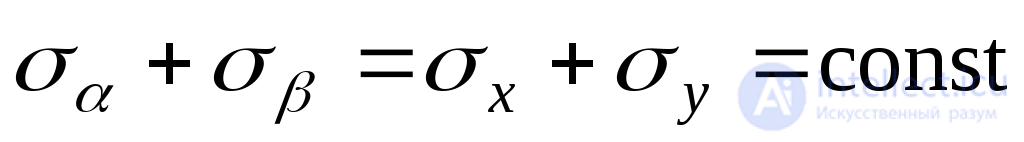 . (9.16)
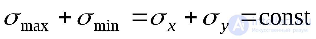
Expression (9.16) is called the invariance condition for the sum of normal stresses acting on two mutually perpendicular sites: at this point, the algebraic sum of normal stresses acting on any two mutually perpendicular sites is a constant value . This condition is used to verify the correctness of the solution of problems in the study of the stress state at a point.
We study the expression for normal stresses (9.14) at the extremum. To do this, take the partial derivative of the voltage  by
by  and equate to zero:
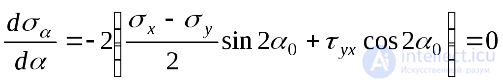 , (9.17)
Where  The angle that is normal to the area under consideration with a positive axis direction
  and at which normal voltage
  reaches the highest value for a given point.
Expression (9.17) represents the value of the shear stress in the main area  . Thus, the shear stress in the area under consideration (
  ) is zero. From this we conclude: the platform, the normal to which is the angle
  with positive axis direction
  is the main site.
Equating the expression in parentheses of formula (9.17) to zero, we find the tangent of a double angle that defines the slope of the main sites:
 . (9.18)
Expression (9.18) gives two mutually perpendicular directions with tilt angles  and
and  over which the main stresses act (Fig. 9.12).
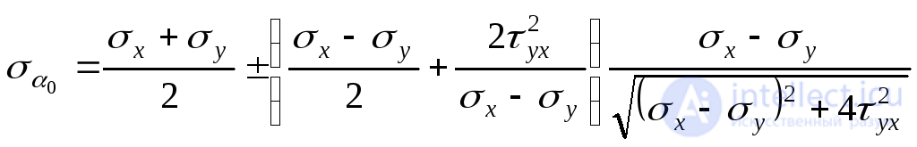
To determine the values of the principal stresses, we substitute the formula (9.14)  . Enduring
  beyond the bracket, we get:
 . (but)
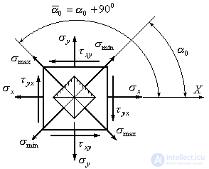
Figure 9.12
From trigonometry it is known:
 . (b)
. (b)
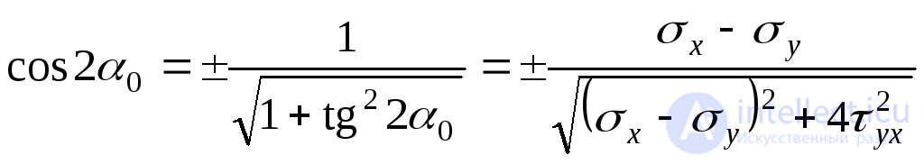
Sign  set because cosines of angles
  and
and 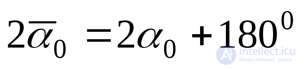 have opposite signs. Substituting (9.18) in (b) and (a), we obtain:
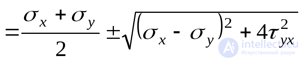 .
.
In this formula, the plus sign corresponds to the maximum principal voltage  , and the “minus” ним the minimum
  . Thus, we finally have:
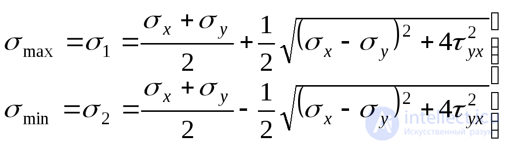 . (9.19)
From the above conclusion it follows that at any initial voltage  at this point there is a parallelepiped, on the faces of which only normal stresses act.
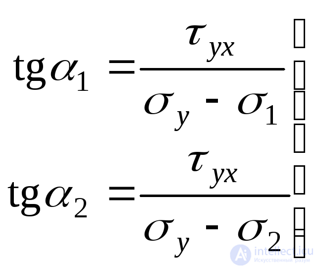
We return to the formula (9.18). It gives two main directions, but does not indicate which of them acts  , and in which
  . To solve this problem, it would be necessary to study the sign of the second derivative
  at
at  and
and  . However, this problem can be solved using expressions similar to those used to determine the direction of the main axes of inertia in the section “Geometric characteristics of plane figures”:
 . (9.20)
Here:  The angle that should be set aside from the positive axis direction
  to the normal to the site in which the maximum voltage
  ;
;  The angle that should be set aside from the positive axis direction
  to the normal to the site in which the minimum voltage
  . The positive angle should be set counterclockwise, the negative should be counterclockwise.
To control the accuracy of determining the position of the main sites, you can use another method given in [2]. Based on the fact that with the rotation of the site in the direction of the tangent stress vector, the normal stress at the site is algebraically increased, the following rule is formulated in [2]:  always passes through two quarters of the coordinate axes, in which the arrows of tangential stresses
  and
and  converge.
We take as the initial site, in which the main stresses act (Fig. 9.13).
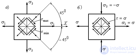
Figure 9.13
Counting the angle  from direction
  write the expressions for
  and
and  using formulas (9.12), (9.14), setting in them
  ,
,  , but
, but  :
:
 ; (9.21)
 . (9.22)
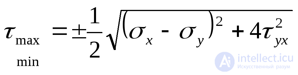
From formula (9.22) it follows that for  double angle sine
  , tangential stresses have extreme values:
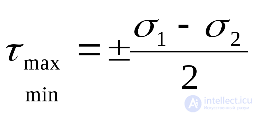 . (9.23)
Extreme tangential stresses at a point are equal to the half-difference of the main stresses and act on sites inclined to the main sites at an angle of 45 0 (Fig. 9.13, a).
Substituting (9.19) into (9.23), we obtain the expression  through the source voltage
  and
and  :
:
 . (9.24)
In the particular case when two main stresses act on the boundaries of the prism  (Fig. 9.13b), the extreme tangential stresses (9.23) are numerically equal to the principal stresses:
 ,
,
and normal stresses on sites with extreme tangential stresses in this case are equal to zero. Such a case of a stress state is called a pure shear , and the areas on which one shear stress acts are called pure shear sites .
Example 9.2 Normal stresses on the sites  MPa
MPa  MPa, shear stress
  MPa Identify normal
  ,
,  and tangents
  ,
,  stresses in areas normal to which is inclined with respect to the axis
  at angles respectively
  and
and  , if a
  =
=  ,
,  =
=  (Fig. 9.14).
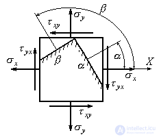
Figure 9.14
Decision:
To determine the normal voltage in the site  we use the expression (9.14):

 MPa
MPa
Normal voltage on site  we find using expression (9.15):

 MPa
MPa
To verify, we use the invariance condition (9.16):
 ;
;  .
.
Tangential stress  we define from the expression (9.12):
 MPa
MPa
Shear stresses acting on the site  :
:
 MPa
MPa
In accordance with the law of paired tangential stresses (9.8):
 .
.
Therefore, the problem is solved correctly. Direction of normal and tangential stresses acting on the sites  and
and  We will show in Fig. 9.15.
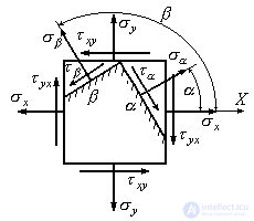
Figure 9.15
Example 9.3 Determine the magnitude of the main stresses  and
and  and directions of the main stresses (Fig. 9.16, a). Draw the main pads and the main stresses in the figure.
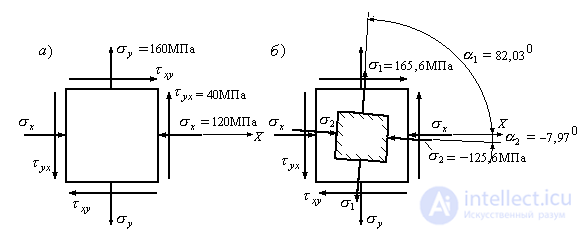
Figure 9.16
Decision:
1. Determine the maximum normal stresses from the expression (9.19):
 =
=
 MPa
MPa

 MPa
MPa
To verify, we use the invariance condition (9.16):
 ;
;  .
.
We find the direction of the main stresses using expressions (9.20):
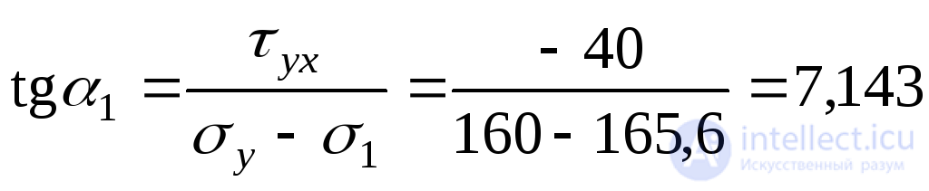 ;
;  ;
;
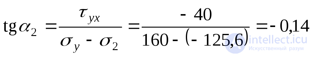 ;
; 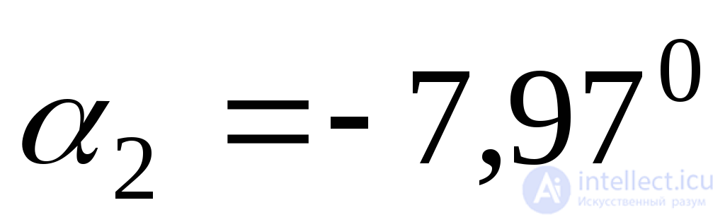 .
.
To verify the correctness of the solution, we add the absolute values of the angles  and
and  . Since the main axes are mutually perpendicular, the sum should be an angle of 90 0 :
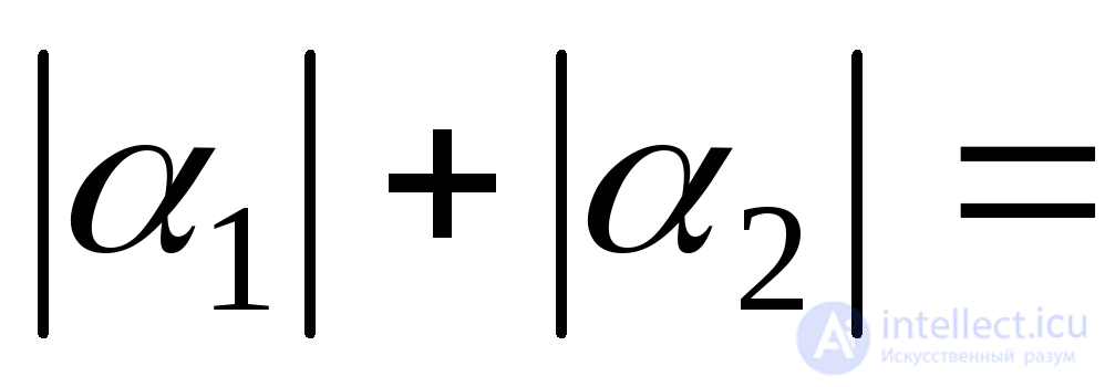
 .
.
The decision is correct. We postpone the found angles in the figure (Fig. 9.16, b) and put down the values of the main stresses.
Example 9.4 Determine the normal, tangential, and principal stresses at point A, shown in the cross-section of the bent beam, if the bending moment in the section is  kNm, shear force -
  kN Find the position of the main sites, depict them in the figure, show the directions of the main stresses.
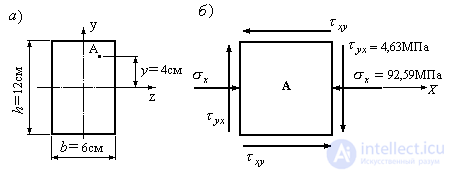
Figure 9.17.
Decision:
1. Calculate the moment of inertia of the cross section relative to the neutral section line  shown in Fig. 9.17a and determine the magnitude of the normal stresses and shear stresses at point A of the section:
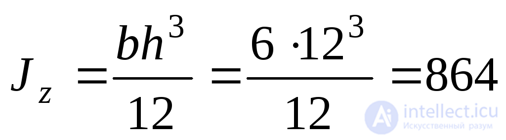 cm 3 ;
 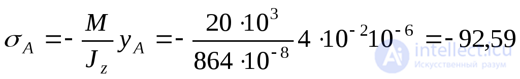 MPa;
MPa;
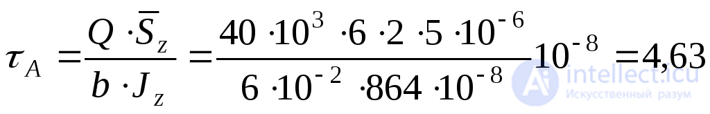 MPa
MPa
2. Cut out an elementary area around point A and apply normal and tangential stresses acting at point A to its faces (Fig. 9.17b).
3. Determine the main stresses at point A:
 MPa;
MPa;
 MPa
MPa
To verify, we use the invariance condition (9.16):
 ;
; 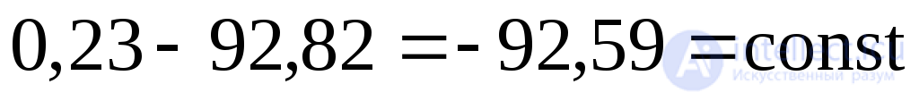 .
.
We find the direction of the main stresses using expressions (9.20):
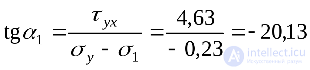 ;
; 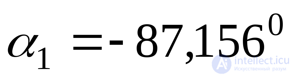 ;
;
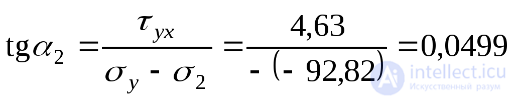 ;
;  .
.
To verify the correctness of the solution, we add the absolute values of the angles  and
and  . Since the main axes are mutually perpendicular, the sum should be an angle of 90 0 :

 .
.
The decision is correct. We postpone the found angles on the figure (Fig. 9.18) and put down the values of the main stresses.
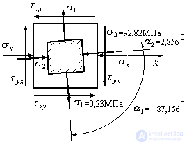
Fig. 9.18

Comments
To leave a comment
Strength of materials
Terms: Strength of materials