Lecture
| Normal stresses at an arbitrary point of the cross-section of the beam during direct bending are determined by the formula: |
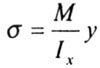 |
| where M is the bending moment in the considered cross section, |
| y is the distance from the considered point to the main central axis, perpendicular to the plane of action of the bending moment, |
| l x - the main central moment of inertia of the section. |
| The greatest tensile and compressive normal stresses in a given cross section arise at the points furthest from the neutral axis. |
| They are determined by the formulas: |
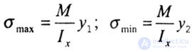 |
| where y 1 and y 2 are the distances from the main central axis x to the most distant stretched and compressed fibers. |
| For plastic beams, when |
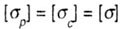 |
(Where  - permissible stresses for the material of the beam, respectively for tension and compression), apply sections that are symmetrical about the central axis. - permissible stresses for the material of the beam, respectively for tension and compression), apply sections that are symmetrical about the central axis. |
| In this case, the strength condition will take the form |
 |
Where 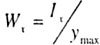 - the moment of resistance of the cross-sectional area of the beam relative to the main central axis: - the moment of resistance of the cross-sectional area of the beam relative to the main central axis: |
 |
| h is the height of the section |
| M max - the largest in absolute value bending moment, |
 - allowable stress of the material for bending. - allowable stress of the material for bending. |
| In addition to the strength condition, the beam must also satisfy the cost-effectiveness condition. |
| The most economical are such cross-sectional shapes, for which with the lowest material expenditure (or with the smallest cross-sectional area) the greatest value of the resistance moment is obtained. To make the section shape rational, it is necessary, if possible, to distribute the section farther from the main central axis. |
| For example, an I-beam standard beam is about seven times stronger and thirty times stiffer than a square cross-section beam of the same area, made of the same material (Fig. 4.15). |
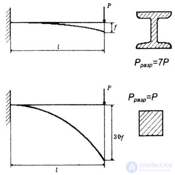 |
| Fig. 4.15 |
| It must be borne in mind that when the position of the section changes with respect to the actual load, the strength of the beam changes significantly, although the sectional area remains unchanged. |
| In most cases, with an increase in the moment of inertia of a section, its moment of resistance also increases, but exceptions are possible when an irrational increase in the moment of inertia leads to a decrease in the moment of resistance, i.e. reduce the strength of the timber. |
| For beams of brittle materials, differently resisting tension and compression, the design formulas for the selection of the section are: |
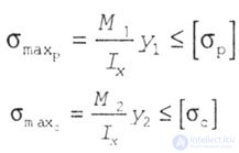 |
| where M 1 and M 2 are the largest in absolute value bending moments in dangerous sections, respectively, for stretched or compressed fibers. |
| For beams from brittle cast iron materials |
 |
| cross sections that are asymmetrical about the neutral axis should be used, for example: T-shaped, asymmetrical I-shaped, U-shaped (Fig. 4.16). |
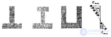 |
| In this case, it is advisable to position the cross section so that the maximum tensile and maximum compressive stresses in the dangerous sections of the beam are simultaneously equal to the corresponding allowable stresses. |
| In all previous cases, the load acted on the beam in only one direction, and the cross-sectional shape of the beam was optimized based on this condition. In some engineering and in most natural objects, the load may act in different directions. Approximately so the load is distributed in the lamppost, leg of the chair, bamboo or leg bones. In these cases, round hollow tubes behave more reliably (Fig. 4.17). |
| However, there are other ways to increase the strength of the structure. This is a prestress. |
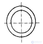 |
| Fig. 4.17 |
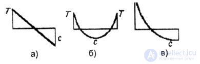
| For example a tree that is subjected to bending loads caused by wind pressure. When compressed wood works much worse than when stretched. When the compressive stress reaches 30 MN / mg, the tree begins to break. It became known that the tree trunk is tense. Somehow the tree grows so that the outer layers of the wood are usually stretched (up to about 15 Mn / m), while the inner ones are compressed. The approximate distribution of pre-stress in the cross-section of the trunk is shown in Fig. 4.18.6, the stresses only from bending - in Fig. 4.18, and and total pressure - on fig. 4.18, c. |
 |
| Fig. 4.18 |
| Wood reduces the maximum amount of compressive stress by about half, although the maximum tensile stress increases, but the tree can cope with it completely. |

Comments
To leave a comment
Strength of materials
Terms: Strength of materials