Lecture
| Consider an example of constructing plots of transverse forces Q and bending moments M x |
|
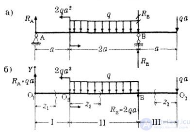 |
| Fig. 5.2 (a, b) |
|
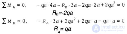 |
| Since the reaction of R B with a minus, we change the chosen direction to the opposite (Fig. 5 2,6). |
| Check: |
 |
| The values of the reactions found are shown in Fig. 5.2 b. |
|
|
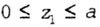 |
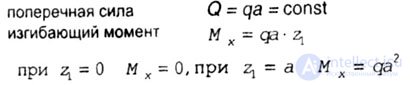
| The origin of coordinates is chosen at the leftmost point O 1 . Consider the equilibrium of the cut-off part of the beam (Fig. 5.3). |
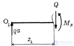 |
| Fig. 5.3 |
| Internal forces arise in the section: |
 |
| Section II O 2 B; |
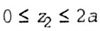 |
| The origin of the coordinates is transferred to the beginning of the O 2 segment (Fig. 5.4). |
 |
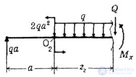 |
| Fig. 5.4 |
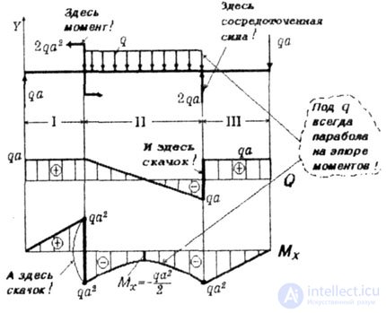
| On the 2nd segment in the moment equation, the arguments (Z 2 ) have the 2nd degree, which means that the plot will be crooked of the second order, i.e. parabola. |
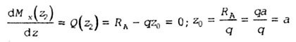
| In the second section, the transverse force changes sign (the beginning of the section + ga, and at the end -ga), then on the plot M x there will be an extremum at the point where Q = 0. Determine the coordinate of the section in which the value M x is extreme, equating the expression of transverse force on this site is zero. |
 |
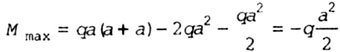
| Determine the magnitude of the extreme moment: |
 |
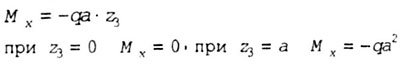
| Section III VO 3 . |
 |
| The origin of coordinates in the third section is placed at the rightmost point of O 3 (Fig. 5.5). |
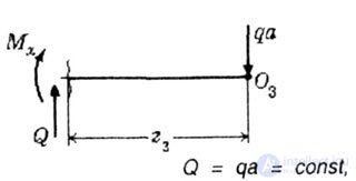 |
| Fig. 5.5 |
| Here |
 |
|
 |
| Fig. 5.6 |
| 6. Check the correctness of plotting. |

Comments