Lecture
| GEOMETRICAL CHARACTERISTICS OF FLAT SECTIONS | |||||||||
| The simplest types of stress state of core structural elements are: tension, torsion and bending. Basic design formulas for determining stresses and strains: | |||||||||
|
|||||||||
| * - N. M K , E, F, G, l C do not change along the axis of the rod, | |||||||||
| ** - torsion of rods of circular cross section, | |||||||||
| *** - straight bend. | |||||||||
| The right sides of the formulas for calculating stresses have an identical structure in the form of a fraction. In this case, internal force factors are in the numerator, and in the denominator - the geometric characteristics of the cross sections: | |||||||||
| F is the cross-sectional area, W p and W x are the polar and axial moments of the section resistance. | |||||||||
| When calculating the deformations, the denominators of the formulas also contain geometric characteristics of the cross sections, for example, l p and l x are the polar and axial moments of inertia of the cross section. | |||||||||
| The task of calculating these quantities is complicated by the fact that all moments of resistance and moments of inertia of sections should be determined relative to the main central axes of the section. Therefore, it is necessary to begin the calculation by determining the coordinates of the center of gravity of the section and finding out which pair of axes passing through it is the main one. | |||||||||
| When calculating the stability will also meet the geometric characteristics of the sections, namely the minimum moment of inertia. | |||||||||
| Information on the distribution of internal force factors in the cross sections of the rod along its longitudinal axis at a given loading is usually obtained on the basis of the corresponding plots for the longitudinal and transverse forces, bending and torsional moments. | |||||||||
| The values of the geometric characteristics of the sections can be obtained in two ways: | |||||||||
|
|||||||||
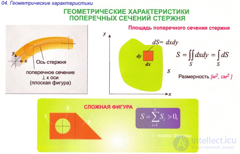
| The simplest characteristic of the strength and stiffness of the rod, depending on the shape and size of the cross section, is F - the cross-sectional area. But this value is used directly in the calculations only when the stresses are uniformly distributed over the cross section, that is, when the rod is stretched or compressed. | |||||||||
| When torsion and bending, the stresses in the cross section are unevenly distributed. Therefore, the calculation formulas for stresses include not only the geometric characteristics of the section, but also additional geometric parameters indicating the location of those section points where the stresses will be extreme for a given type of loading. | |||||||||
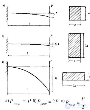
| Consider this on the example of a rod of square cross section, experiencing bending deformation (Fig. 4.1, a). | |||||||||
| If the height is, the prince is doubled and the width is halved (Fig. 4.1.6), then the cross-sectional area will not change rod will need twice the strength (in relation to the original version). | |||||||||
| If you now rotate the rod 90 ° (Fig. 4.1, c), then its deformation will increase 4-fold compared with the original version (Fig. 4.1, a), and the breaking force will be halved. | |||||||||
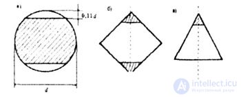
| It is quite logical to assume that reducing the cross-sectional area reduces the strength of the rod. However, in some cases, the removal of part of the material of the rod increases its strength. | |||||||||
| If the round section is cut segments, as shown in (Fig. 4.2, a), then the strength of the rod increases, reaching a maximum value when the arrow of the segment being cut is 0.11 d. | |||||||||
 |
|||||||||
| Fig. 4.1 (a.b.v) | |||||||||
| It can be shown that removing the vertices of a square or a triangle (Fig. 4.2, b, c) leads to an increase in strength by 5%. | |||||||||
 |
|||||||||
| Fig. 4.2 (AB) | |||||||||

Comments
To leave a comment
Strength of materials
Terms: Strength of materials