Lecture
The deformation of any elementary parallelepiped can be represented as consisting of a number of separate simple deformations (Fig. 9.23). There are six components of the deformation: three linear (  ) and three angular, shear (
  ) The linear components represent the relative elongation of the edges of the elementary parallelepiped, and the index when designating deformations shows which axis this elongation takes place in parallel. Linear deformations lead to a change in volume and shape (for example, the transition from a cube shape to a parallelepiped shape). Angular deformations are a shift of the elementary parallelepiped with respect to the initial position. A positive shift corresponds to a decrease in the angle between the positive direction of the axes, and a negative shift corresponds to an increase in this angle.
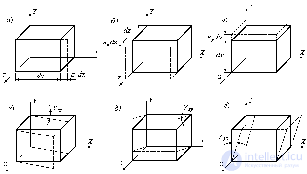
Figure 9.23
The shear angles projected onto the X Y plane are indicated  (or
(or  ) on the plane YZ
  (or
(or  ) and to the plane ZX
  (or
(or  ) In this case, the angular deformations are equal in pairs:
  ;
;  ;
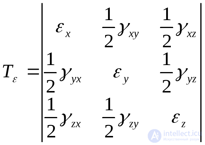
;  . Thus, a deformed state, which is a combination of linear and angular strains for various positions of the coordinate axes, can generally be described by a strain tensor:, including nine components: three relative linear strains
  and six shear angles
  ,
,  ,
,  .
.
 . ( 9.54)
The strain tensor can be divided into the ball strain tensor
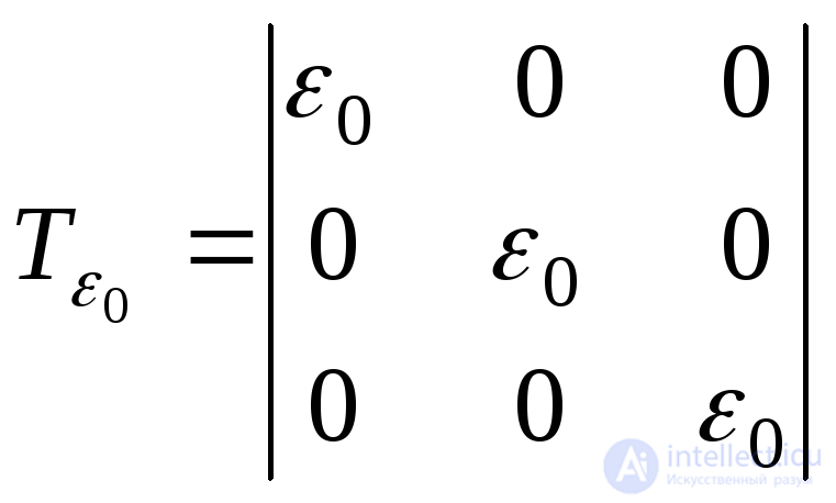 . ( 9.55)
which characterizes the volumetric strain at a point, and the strain deviator:
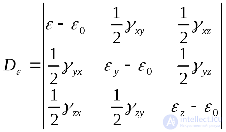 , ( 9.56 )
which characterizes the shape change in the vicinity of the same point.
The elongation of a segment passing through a given point can be expressed in terms of six deformation components of the same point
 , (9.57)
Where  cosines between the direction of the considered segment and the axes of rectangular coordinates.
It can be argued that at each point (by analogy with the stress state) of the body there are three mutually perpendicular directions, called the principal axes of deformation, which have the property that the material in these directions experiences only linear deformations, since the shear is zero.
If we substitute in (9.35) instead of the stress tensor components the strain components, i.e. change  on
on  ,
,  on
on  etc., then you can get a cubic equation that defines the main linear deformations:
 . (9.58)
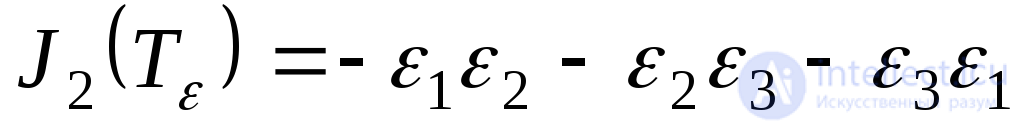
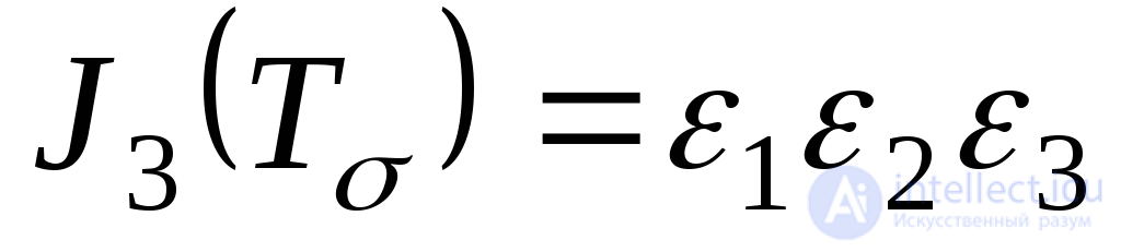
The invariants of the strain tensor will have the form:
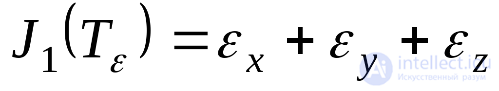 ; (9.59)
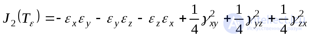 ; (9.60)
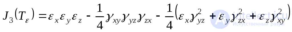 . (9.61)
Expressions of invariants through principal deformations have the form:
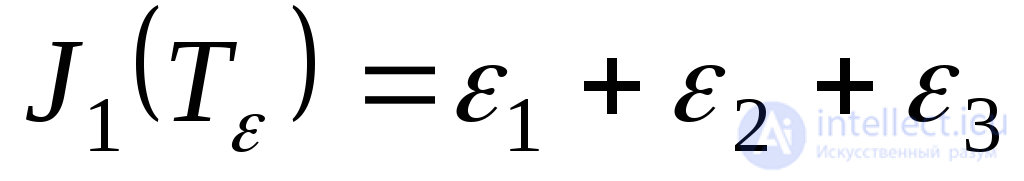 ; (9.62)
 ; (9.63)
 . (9.64)
By analogy with stresses, elongation in the direction perpendicular to the octahedral site will be equal to:
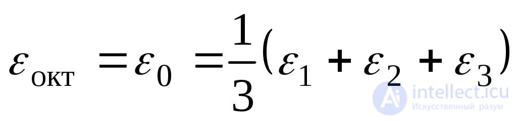 . (9.65)
The relative angular deformation in the octahedral planes has the form:
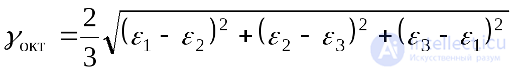 (9.66)
or
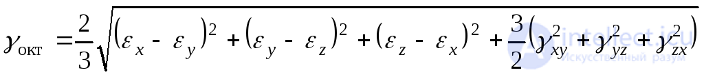 (9.67)
The largest relative shift, by analogy with (9.43), is:
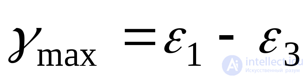 . (9.68)
The strain rate is taken from the expression:
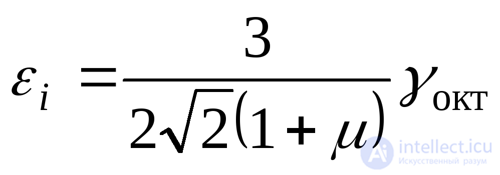 (9.69)
or
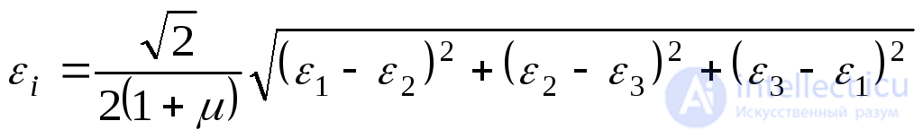 . (9.70)
Here  Poisson's ratio.
Consider an element isolated from a centrally extended rod (Fig. 9.24).
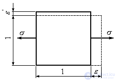
Figure 9.24
The element experiences longitudinal and transverse strains associated with stresses.  formulas:
 ; (9.71)
 . (9.72)
Here:  modulus of elasticity under tension (compression), and
  Poisson's ratio. Elongation deformation is considered positive, shortening - negative.
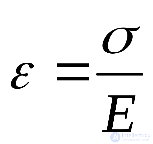
Formula (9.71) expresses Hooke's law under simple tension (linear stress state). We establish a similar relation for the volumetric stress state.
Find the main deformations  expressing them through major stresses
  . For this we use the principle of independence of the action of forces and relations (9.71) and (9.72). Total elongation
  in the direction of stress
  can be represented by three terms:
 ,
,
Where  deformation arising from stress only
  and determined by the formula (9.71), since this deformation is longitudinal with respect to
  (Fig. 9.25a).
 elongation caused by stress
  . It is transverse to
  deformation (Fig. 9.25b), which is determined by the formula (9.72).
 strain caused by stress
  .
.
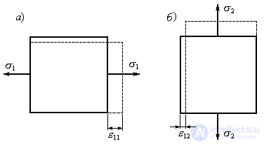
Fig. 9.25
Consequently:
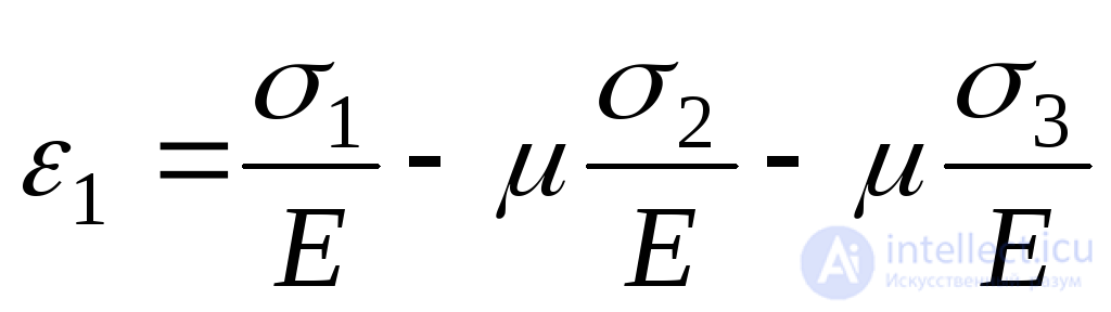 .
.
Applying similar reasoning to the definition  and
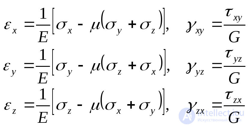
and  , we obtain the formulas of Hooke's law in volumetric stress state (generalized Hooke's law):
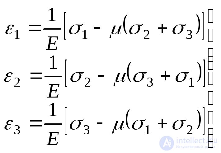 . (9.73)
In these formulas, tensile stress is substituted with a plus sign, and compressive stress with a minus sign.
If one of the three principal stresses is equal to zero, we have a plane stress state. In this case, for example, when  we get:
 . (9.74)
It should be noted that zero voltage does not mean that  also equal to zero. Indeed, for
  we have:
 . (9.75)
At known voltages  and
and  by formulas (9.74) determine the defomation
  and
and  . But in some cases it is necessary to have an inverse relationship. Multiplying the second line of formula (9.74) by
  and adding to the first, we get:
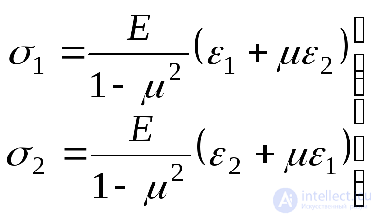 . (9.76)
The resulting formulas are written in relation to the main areas and voltages. However, it should be borne in mind that for nonprincipal sites Hooke's law, connecting normal stresses  and
and  and corresponding extensions
  and
and  has the same form:
 , (9.77)
Where  Сдвиг shift module.
The reason is that, at small strains, the effect of shear on linear strain is a second-order small quantity that can be neglected.
We denote the dimensions of the sides of the elementary parallelepiped before deformation by  (Fig. 9.26a). After deformation, these sizes will increase and become equal
  ,
,  ,
,  (Fig. 9.26b). The initial volume of the box is denoted by
  , and after deformation
  .
.
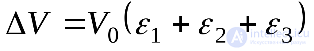
Find the absolute change in the volume of the box:

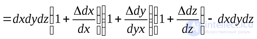 . (9.78)
Here in brackets are relative elongations:
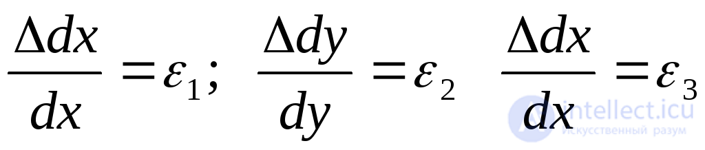 . (9.79)
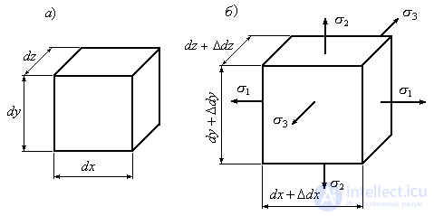
Figure 9.26
Substituting in (9.79) into (9.78) and multiplying the expressions in parentheses, we obtain:
 .
.
Neglecting the products of relative elongations due to their smallness, we have:
 (9.80)
The relative change in volume or relative volumetric deformation takes the form:
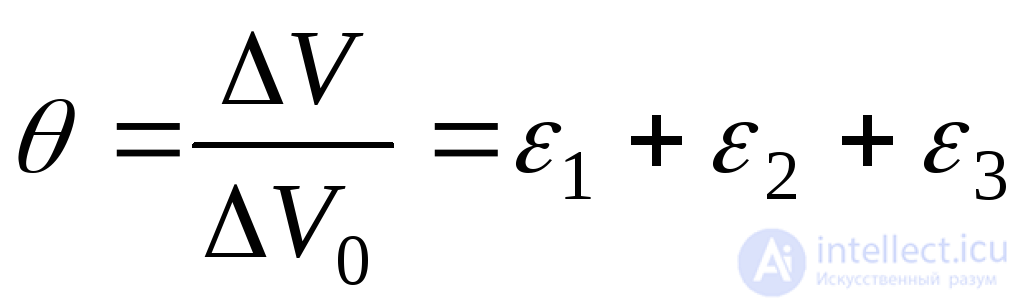 . (9.81)
This formula is valid for both elastic and elastic-plastic deformations.
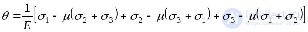
For the elastic stage of the work of the material, one can express the relative change in volume through stress  . To do this, substitute the values
  from expression (9.73) to expression (9.81):
 .
.
After the conversion, we get:
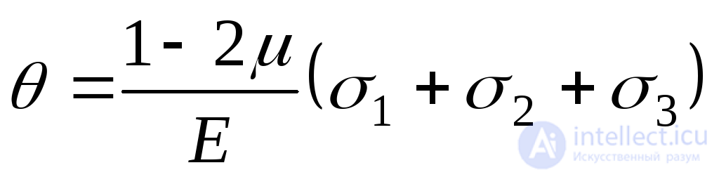 . (9.82)
In particular, with uniform full compression, when 
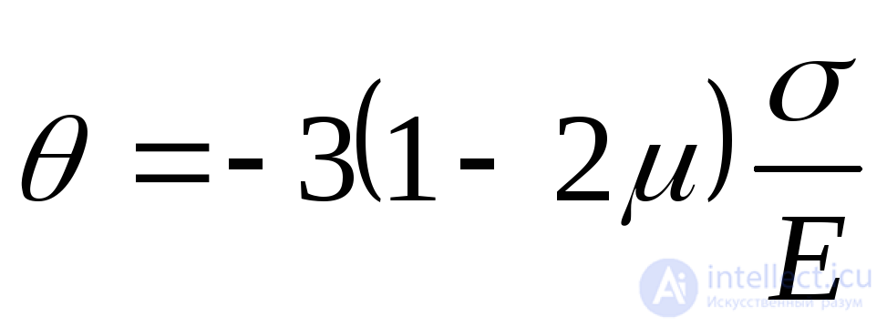 . (9.83)
It follows from expression (9.83) that the Poisson's ratio cannot be greater than 0.5, because otherwise, under full compression, the body will not decrease, but increase in volume, which contradicts the physical meaning. This conclusion is confirmed by experimental data. In nature, no materials were found for which the Poisson's ratio would be more than 0.5.
There are materials (for example, paraffin) in which the Poisson's ratio approaches 0.5. In this case, with full compression, there will be no change in volume. Thus, paraffin in its elastic properties approaches an incompressible fluid.
For ductile steel, the Poisson's ratio is also close to 0.5. In this regard, the volume of the plastic steel sample does not change during flow.
Now we calculate the average voltage (Fig. 9.26, b):
 .
.
Substituting the average voltage in the formula (9.82), we obtain:
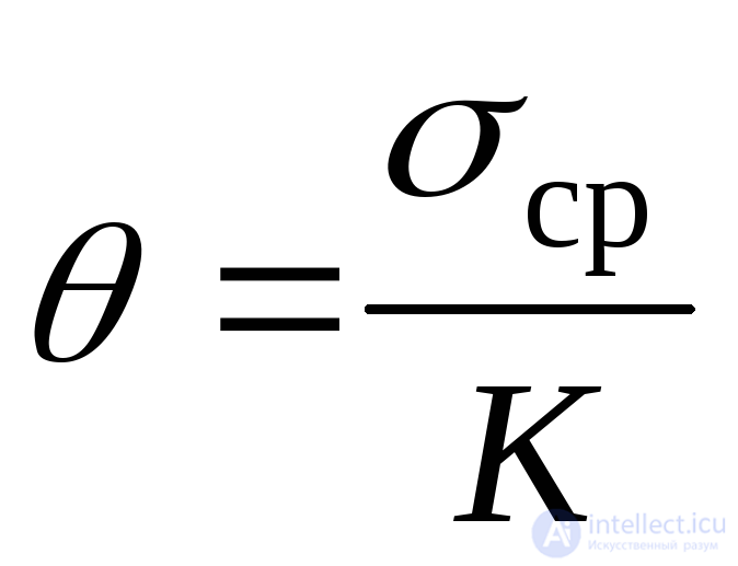 , (9.84)
Where
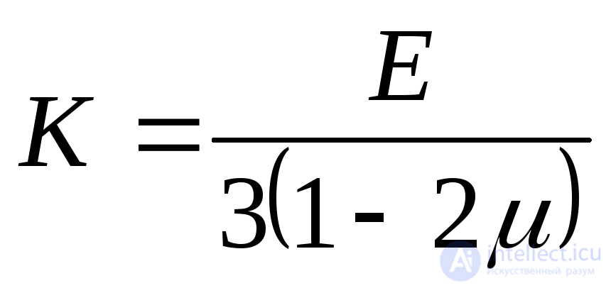 . (9.85)
Value  is called the bulk strain modulus, and expression (9.84) is called the Hooke volumetric law . In accordance with this law, the relative change in volume is proportional to the average voltage

Comments
To leave a comment
Strength of materials
Terms: Strength of materials