| |
| The moments of inertia of the cross section are included in the formulas for stresses and strains. |
| The axial moments of inertia of a section with respect to the axes X and Y (Fig. 4.3) are defined integrals of the form |
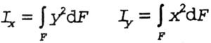 |
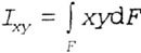
| The centrifugal moment of inertia of a section with respect to two mutually perpendicular axes x and y is a definite integral of the form (Fig. 4.3) |
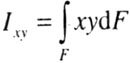 |
| The polar moment of inertia of a section relative to the origin of coordinates o is a definite integral of the form |
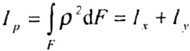 |
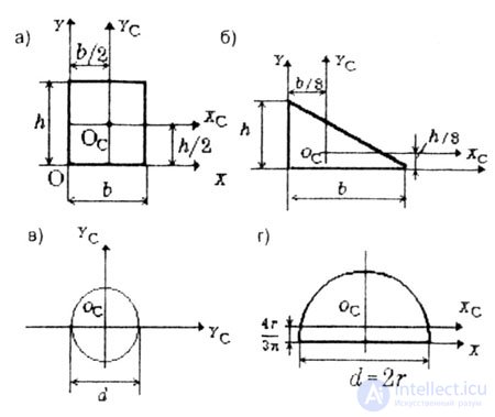
| Below are the moments of inertia of the most common simplest sections: |
|
No
|
I xc
|
I yc
|
I xcyc
|
I c
|
I y
|
I yy
|
|
but)
|
bh 3/2
|
b 3 h / 12
|
0
|
bh 3/3
|
b 3 h / 3
|
b 2 h 2/4
|
|
b)
|
bh 3/36
|
b 3 h / 36
|
-b 2 h 2 // 78
|
bh 3/12
|
b 3 h / 2
|
b 2 h 2/24
|
|
at)
|
Pd 4/64
|
Pd 4/64
|
0
|
-
|
-
|
-
|
|
d)
|
0,11r 2
|
PD / 128
|
0
|
Pd 4/128
|
-
|
-
|
|
| |
 |
| Fig. 4.5 |
| The sign of the centrifugal moment of inertia of a section can often be determined from the section drawing (Fig.4.6). |
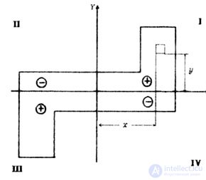 |
| Fig. 4.6 |
| According to the formula |
 |
| Hence, parts of the area located in the I and III quadrants have positive centrifugal moments of inertia, since the products of the x and y coordinates of the elementary areas dF in these quadrants give positive values. Parts of the area located in II and IV quadrants have negative centrifugal moments of inertia. |
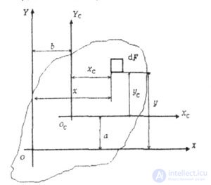
| The moments of inertia about parallel axes, some of which are central (XC0CYC) are determined from the expressions (Fig. 4.7): |
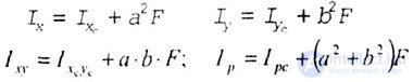 |
| where a and b are the coordinates of the center of gravity of the section O c |
 |
| Fig. 4.7 |
| Coordinates a and b must be substituted into these formulas taking into account their signs. |
| The moments of inertia included in the formulas for determining the strength and rigidity of a structure are calculated relative to the axes, which are not only central but also essential. To determine which axes passing through the center of gravity are the main ones, one must be able to determine the moments of inertia about the axes that are turned relative to each other at a certain angle. |
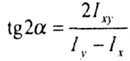
| The dependencies between the moments of inertia during the rotation of the coordinate axes (Fig. 4.8) have the form: |
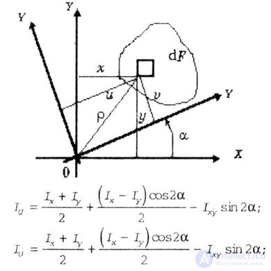 |
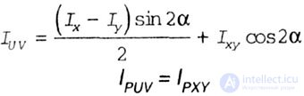 |
| Fig. 4.8 |
Where  - the angle between the axes XOY and UOY. The angle is considered positive if the rotation of the XOY axes occurs counterclockwise. - the angle between the axes XOY and UOY. The angle is considered positive if the rotation of the XOY axes occurs counterclockwise. |
| The main axes of inertia are two mutually perpendicular axes with respect to which the centrifugal moment of inertia of the section is zero. |
| The direction of the main axes of inertia is determined by the equation |
 |
| The main moments of inertia are the axial moments of inertia, calculated relative to the main axes of inertia, which have extreme values |
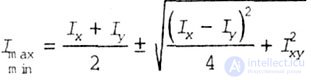 |
| The main axes passing through the center of gravity of the section are called the main central axes, and the moments of inertia about these axes are called the main central moments of inertia. |
| The axis of symmetry of the flat section is | the main central axis of inertia of this section. |
| If a flat section has at least two axes of symmetry non-perpendicular to each other, then all axes passing through the center of gravity of this figure are its main central axes of inertia. The axial moments of inertia of the sectional area, calculated relative to these axes, are equal to each other (Fig. 4.9). |
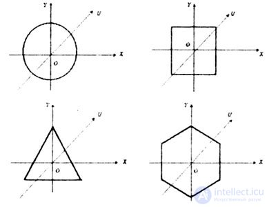 |
| Fig. 4.9 |
| The moments of inertia of complex sections are determined by the formulas |
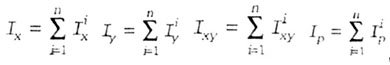 |
Where  - axial moments of inertia; - axial moments of inertia;  - centrifugal moments of inertia; - centrifugal moments of inertia;  - polar moments of inertia of individual section figures. - polar moments of inertia of individual section figures. |

Comments
To leave a comment
Strength of materials
Terms: Strength of materials