Lecture
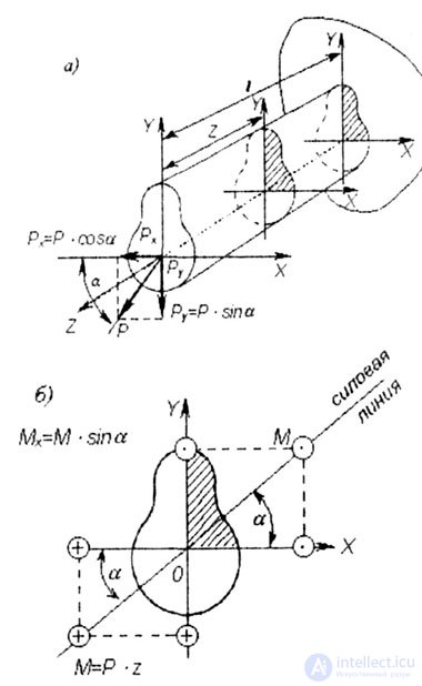
| An oblique bend is a type of bend in which the plane of the load (line of force) of the bending moment does not coincide with any of the main axes of inertia of the cross section of the bar X, Y (Fig. 7.1 a, b). |
| With oblique bending, the acting external forces (moments) are projected onto the main axes of the cross section (Fig. 7.1, b), thereby reducing the task to the case of transverse bending in two main planes. From fig. 7.1, a, b shows that: |
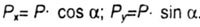 |
| Bending moments in the design section: |
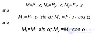 |
| When the direction of the main central axes of inertia is chosen, the first octant will be the positive octant (in Fig. 7.1, a, b it is shaded). |
 |
 |
| Fig. 7.1 |
| The rule of signs. Bending moments in the calculated cross section are considered positive if they cause tensile stresses in the first (hatched) octant. |
| Normal stresses at cross-section points with current x, y coordinates are determined by the algebraic sum of stresses caused by bending moments M x and M y : |
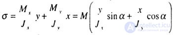 |
where J x and J y are the moments of inertia of the cross section with respect to the main, central axes of inertia of the section X, Y, i.e., they change according to a linear law. The equation of the neutral (zero) line in the section we find, equating  |
| The answers matched. |
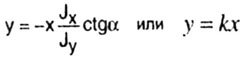 |
| When x = 0, the value of y = 0, i.e., a straight line with the slope k passes through the center of gravity of the cross section. |
| With oblique bending, the neutral line is a straight line that is not perpendicular to the plane of the bending moment, or, which is the same, to the line of force. |
| The line of force is inclined to the X axis at an angle a, therefore, its angular coefficient is equal to: |
 |
| Neutral Line Angle Coefficient: |
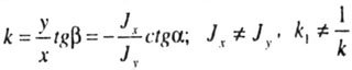 |
| Since, in general, J x is not equal to J y , then k 1 is not equal to - 1 / k, therefore, the zero length is not perpendicular to the line of force, but turned towards the main axis of the minimum moment of inertia. |
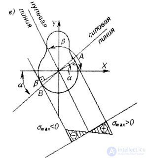
| The neutral line divides the cross section into two zones: |
|
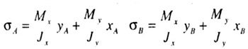
| Maximum magnitude tensile stresses occur at point A with coordinates X a , Y l and maximum compression stresses occur at point B with coordinates X B , Y B (Fig. 7.1, c): |
 |
| We obtain a plot of normal stress in the design section (7.1, c). |
| Strength condition If the material of the rod works equally in tension and compression, the strength condition is written in the form: |
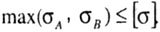 |
| If the material of the rod works in tension and compression is not the same, then the calculation is carried out separately, that is, the strength conditions are checked: |
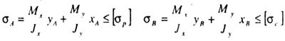 |
| For cross sections with two axes of symmetry: |
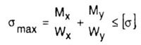 |
| where W x , W y - the moment of resistance of the cross section relative to the main, central axes of inertia X, Y. |
| Deflections in oblique bending. The deflection of the end of the console from the action of P x is directed along the X axis and is equal to: |
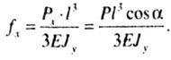 |
| The deflection from the action of P y is directed along the Y axis and is equal to: |
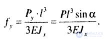 |
| Console end camber module |
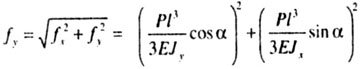 |
| The angle of the vector f to the X axis |
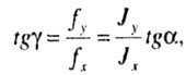 |
| i.e. the slope |
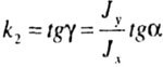 |
| multiplying k by k 2 we get: |
 |
| which indicates that the zero line and the direction of the total deflection are mutually |

Comments
To leave a comment
Strength of materials
Terms: Strength of materials