
Lecture
Switching device — a device intended to close or open current in one or more electrical circuits.
In general, all switching devices can be divided into two types:
Contact switching device
A switching device that performs the switching operation by moving its contact parts relative to one another .
Contactless switching device
A switching device that performs the switching operation without moving or destroying its parts (based on semiconductor or gas-discharge devices, magnetic amplifiers, etc.) .
The main electrical switching devices are :
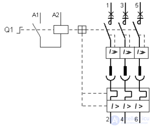
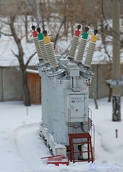
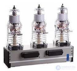
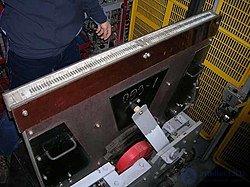
High-voltage circuit breaker — a switching device designed for operational closing and opening of individual circuits or electrical equipment in a power system under normal or emergency conditions, with manual, remote or automatic control.
A high-voltage circuit breaker consists of: a contact system with an arc-extinguishing device, current-carrying parts, a housing, an insulating structure and an operating mechanism (for example, an electromagnetic drive, a manual drive).
In accordance with GOST R 52565-2006, circuit breakers are characterized by the following parameters:
Cycle 1: O — tdead — CO — 180 — CO;
Cycle 2: O — 180 — CO — 180 — CO,
where O — opening operation, CO — closing operation followed immediately by opening, 180 — time interval in seconds, tdead — the minimum dead-current pause guaranteed for circuit breakers during AR (the time from arc extinction to the appearance of current at the subsequent closing). For circuit breakers with AR it must be within 0.3…1.2 s, and for circuit breakers with HSAR (high-speed AR) — 0.3 s.
Medium- and high-voltage circuit breakers (rated voltage 6—220 kilovolts) with a high breaking current (up to 50 kiloamperes) are used at power plants and substations. These breakers are a fairly complex design, operated by electromagnetic, spring, pneumatic, or hydraulic mechanisms. Depending on the medium in which arc quenching takes place, a distinction is made between air-blast circuit breakers, in which the arc is quenched by compressed air; oil circuit breakers, in which the contacts are placed in a tank of oil and the arc is quenched by oil vapor; electromagnetic circuit breakers (generally up to 10 kV), with so-called magnetic blow-out and arc-quenching chambers with narrow slots or grids; SF6 (gas-insulated) circuit breakers, which use the dielectrically strong gas SF6 — «SF6 gas»; and vacuum circuit breakers, in which arc quenching takes place in a vacuum — in the so-called vacuum interrupter (VI). The insulating medium, in addition to quenching the arc, also provides the dielectric strength of the gap between the contacts in the open position, which in turn determines the required contact travel.
By arc-quenching method
By purpose
By type of installation
By placement category and climatic design
In air-blast circuit breakers (ABCBs), the energy of compressed air is used both as the driving force that moves the contacts and as the arc-extinguishing medium. The operating principle of the arc-extinguishing device (of the ABCB) is that the arc forming between the contacts is subjected to intensive cooling by a stream of compressed air discharging into the atmosphere. As the current passes through zero, the arc temperature drops and the resistance of the gap increases. At the same time, mechanical disruption of the arc column occurs, and charged particles are carried out of the gap.
Structurally, air-blast circuit breakers are divided into:
The insulating and arc-quenching medium of these breakers is sulfur hexafluoride SF6 (SF6 gas). The breakers are three-pole devices whose poles either share a single (common) frame and are operated by a single drive mechanism, or each of the three poles has its own frame and is operated by its own drive mechanism (a breaker with independent-pole operation).
The operating principle of these devices is based on extinguishing the electric arc (which arises between the diverging contacts when the current is interrupted) with a flow of SF6 gas.
There are two sources of gas flow generation:
The first source predominates when interrupting small currents, and the second when interrupting large currents.
Breaker pole
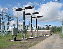
Live-tank (column) design. The pole is a vertical column consisting of two (or more) insulators, the upper one of which houses the arc-extinguishing device (AED), while the lower one serves as a support for the AED and provides it with the required insulation clearance from the grounded frame. Inside the support insulator is an insulating operating rod connecting the movable contact of the AED to the drive mechanism of the device.
Dead-tank design. The pole is a metal cylindrical tank on which two insulators are mounted, forming the high-voltage bushings of the breaker. In this type of breaker, the AED is located inside a grounded metal enclosure.
Combined design. The pole is a spherical metal enclosure on which porcelain insulators are mounted, forming the high-voltage bushings of the breaker; the arc-extinguishing device is located in one of them, while built-in current transformers are located in the other.
A filter is usually installed in the upper part of the insulator to absorb moisture and the decomposition products of the SF6 gas caused by the electric arc. The filtering element in it is an activated adsorbent — synthetic zeolite NAX.
All modern breakers are also fitted with a safety (pressure-relief) valve — a device with a thin-walled diaphragm that ruptures at the pressure arising from an internal short circuit, but that does not reach the value at which the insulators themselves are tested.
Arc-extinguishing device
The arc-quenching device is designed to ensure rapid quenching of the electric arc that forms between the breaker's contacts when they open. Developing a rational and reliable design for an arc-quenching device presents considerable difficulties, since the processes occurring during arc quenching are extremely complex, insufficiently studied, and governed by many factors that cannot always be foreseen in advance. Therefore, the final design of an arc-quenching device can be considered complete only after it has been experimentally verified.
Modern circuit breakers are equipped with a self-blast (auto-puffer) type arc-quenching device, which demonstrates its calculated advantages when interrupting large currents.
The arc-quenching device (AQD) contains fixed and moving contact systems, each of which has main contacts and arcing contacts fitted with elements made of arc-resistant material. The main contact of the fixed system and the arcing contact of the moving system are of the socket type, while the main contact of the moving system and the arcing contact of the fixed system are of the pin type.
In addition to the main and arcing contacts, the moving system contains a fixed current-carrying sleeve connected to the AQD's current terminal; a piston device that creates elevated pressure in the sub-piston chamber during interruption; and two PTFE nozzles (large and small) that direct gas flows from the high-pressure zone to the zone where the arcing contacts separate. The large nozzle also prevents radial displacement of the moving system's contacts relative to those of the fixed system, since it never leaves the guide bushing of the main fixed contact.
The main contact of the moving system is a stepped copper sleeve, the narrow part of which is shaped to fit into the socket-type main contact of the fixed system, while the wide part has two grooves in which current-collecting (closed wire) coil springs are located, remaining constantly in contact with the fixed current-carrying sleeve that surrounds them.
Gas system
The gas system of the apparatus includes:
The SF6 density indicator (density sensor) has three pairs of contacts: one, which closes when the SF6 density drops significantly due to leakage, is intended to give a signal (for example, a light signal) that the columns need to be refilled; the other two, which open when the SF6 density falls to an impermissible level, are intended to block control of the breaker or to automatically trip the apparatus while simultaneously blocking closing (as determined by the substation design).
Operating mechanism
Breaker operating mechanisms provide control of the breaker — closing, holding in the closed position, and opening. The mechanism shaft is connected to the breaker shaft by a system of levers and links. The breaker's operating mechanism must ensure the necessary reliability and speed of operation, and, with electrical control, the lowest possible power consumption.
Two types of operating mechanisms are used in SF6 circuit breakers:
Spring-operated mechanism:
Spring-hydraulic operating mechanism:
The circuit breaker is the most critical apparatus in a high-voltage system; during faults it must always ensure reliable operation. If a breaker fails, the fault develops further, leading to severe damage and large material losses associated with loss of power supply and the shutdown of large enterprises.
In this regard, the main requirement for circuit breakers is an especially high reliability of operation under all possible operating conditions. Interruption of any load by a breaker must not be accompanied by overvoltages that are dangerous to the insulation of the installation's components. Since a short-circuit condition is the most severe for the system, the breaker must ensure that the circuit is interrupted in the shortest possible time.
General requirements for the design and characteristics of circuit breakers are established by the standards:
Taking a breaker out of service for inspection and repair involves considerable difficulty, since it is necessary either to switch to a different switchgear configuration or simply to disconnect consumers. For this reason, a breaker must be capable of the greatest possible number of short-circuit interruptions without inspection and repair. Modern circuit breakers can interrupt up to 15 short circuits at full breaking capacity without inspection.
Low-voltage switches
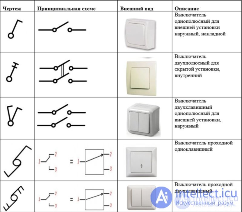
Designation of a switch on an electrical diagram: Designation of switches and outlets on drawings
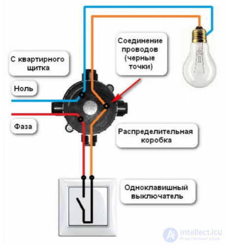
Progress does not stand still even where switches are concerned; they are made ever more convenient, attractive, and functional, and are adapted for use in different situations. Hence the variety of types:
Another classification divides them into types according to the operating principle of the switching mechanism.
Under the term "Master switch" one usually means a switch that, when pressed, turns off all lighting groups as well as all outlet groups connected to it
Globally, there are two types of master switches:
The first option is the correct one; it can be implemented using traditional wiring with minor modifications, while the second option conceals drawbacks that are not obvious at first glance.
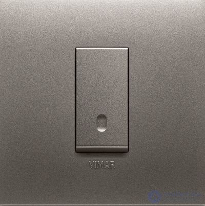
QUID makes it possible to correctly implement the central shutdown scenario even in traditional systems
The central shutdown scenario is convenient for turning off all lighting; it is triggered by a doorbell-type switch with backlighting. Such an illuminated switch is appropriately placed at the head of the bed, near the front door, and in other places where central shutdown of all or selected lighting or outlet groups may be needed.
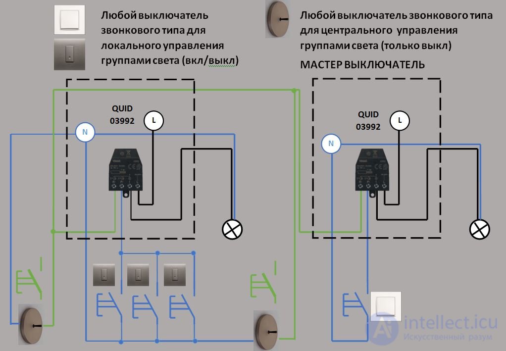
To connect a controlled outlet that will participate in the central shutdown scenario, but will not be centrally turned on and will only be turned on from a local switch, the following circuit can be used (using a relay and doorbell buttons)
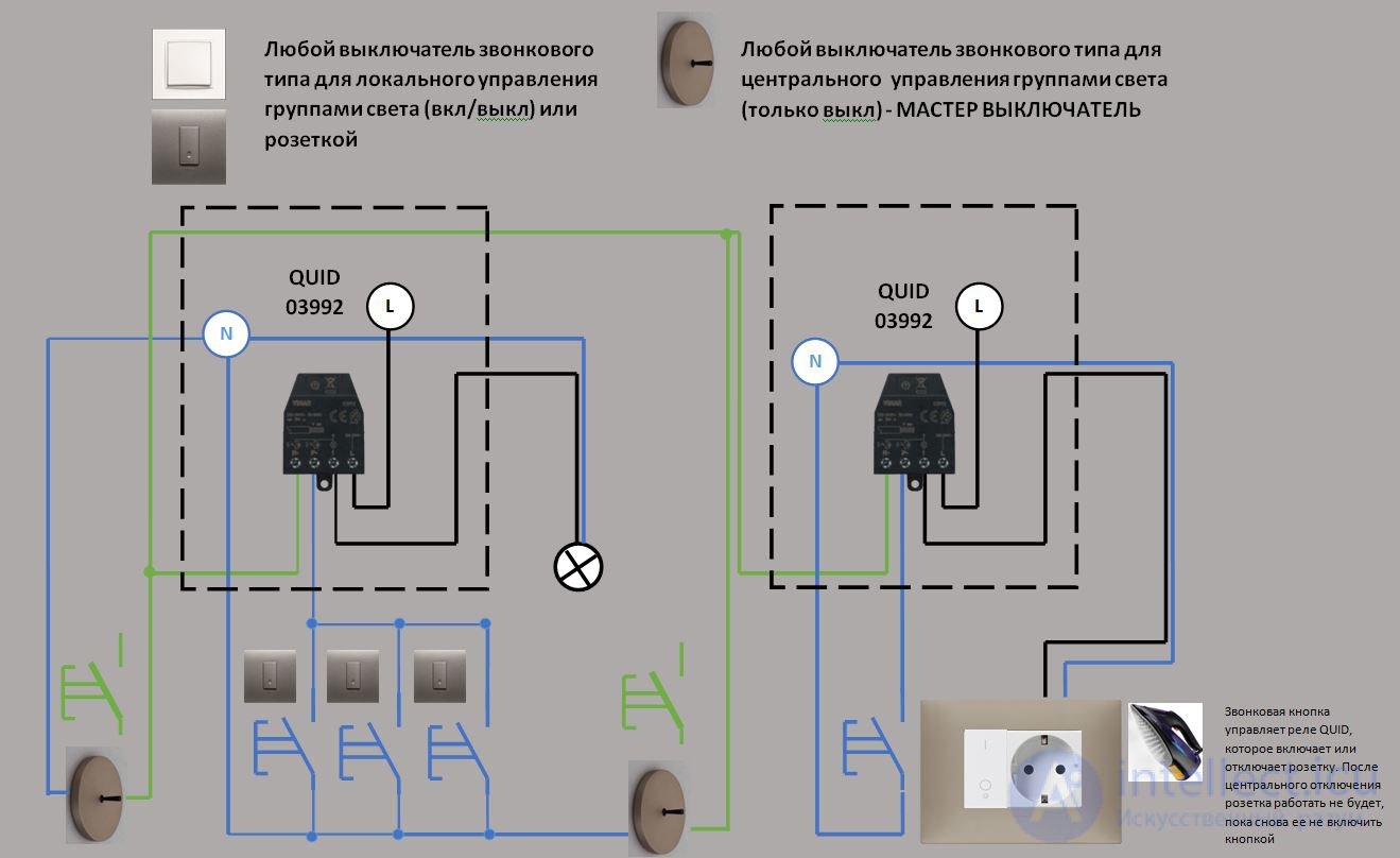
This type of central shutdown is quite popular among those who want additional convenience for minimal money
At first glance, this type of switch can save time and electricity, as well as provide additional safety. We disagree with this, and we will now explain why.
An ordinary switch is connected to the control terminals of a contactor, to which, in turn, all lighting groups and controlled outlets are connected. When the master switch is on, the contactor passes current through itself, powering all connected devices. When the switch is turned off, the contactor interrupts the power supply.
If you turn on all the lights in the house from local switches, then using the master key you will turn off all the lights and then turn them on simultaneously, which entails certain drawbacks.
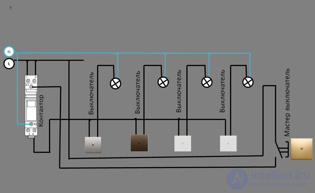
Suppose you live in a two-story house, during the construction of which the crew grouped all the lighting groups, as well as some outlet groups, together and connected them through a contactor located in the panel,
You are about to leave the house, but you don't remember whether the lights are off in all the rooms, and moreover you suspect that the iron was left on in the laundry room, but you're not worried, because with one press of the key you turn everything off and calmly leave the house.
After a while, someone from your family arrives, earlier than you.
To use the lights and outlets, they need to turn on the master switch. After that, all the lights in the apartment come on, and the iron is energized again.
But the person who arrived doesn't know this...
It turns out that a contactor-based master switch only creates an illusion of convenience, but in reality causes nothing but problems.
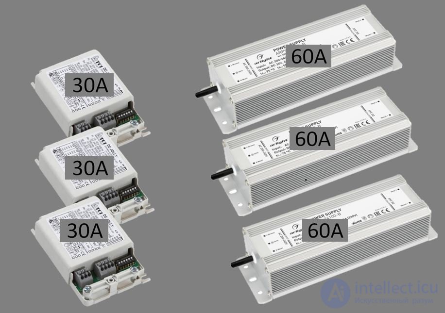
On top of that, the power supplies used for both light fixtures and LED strips have high inrush currents — from 30 to 60 A — and there can be dozens of them, so on a cold start the current surge can reach a thousand or even several thousand amperes. A 2.5 mm² wire is rated for a current of 25 A. Yes, the peak values last only fractions of a second, but they have a negative effect on the equipment and can trigger tripping of the protective circuit breaker and other problems.
The inability to use local switches once the main disconnect has de-energized the system makes it pointless to use such a scenario when someone remains in the house or apartment.
QUID master switches for controlling lighting and curtains can be located at the entrance/exit of the house or apartment, as well as in the bedroom or study — in general, in places where the function of switching off all lighting loads, as well as centralized curtain control, might be needed.
It is worth noting that such a switch should be positioned so as to rule out accidental pressing while someone is in the house. It should be visually distinct from the other switches — whether by color or by a pictogram. It could even be a key-operated switch of this kind.
As for the placement of a contactor-based master switch, everything said above applies to it as well, only with stricter requirements regarding unauthorized or accidental access. In essence, in this case such a main element plays the role of the knife switch, which it, in fact, duplicates
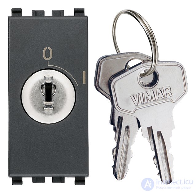
When using "Smart Home" control systems, any switch can be assigned as the master switch, since this is exactly the "turn everything off" scenario, and it works correctly, although it already requires skills in setup and connection.
An automatic circuit breaker is a contact switching device (mechanical or electronic) capable of making, carrying, and breaking currents under normal circuit conditions, as well as making, carrying for a specified (rated) time, and automatically breaking currents under specified abnormal circuit conditions, such as short-circuit currents.
History of the invention of automatic circuit breakers
The line protection automatic breaker was invented by the American scientist Charles Grafton Page in 1836. The first design of an automatic circuit breaker was described by Edison in 1879, while his commercial power supply system used fuses. The design of modern automatic circuit breakers was patented by the Swiss company Brown, Boveri & Cie in 1924.
GOST 9098-78 establishes the following classification of circuit breakers:
In the standards of the USSR and Russia, selective circuit breakers are circuit breakers with a time delay (0.25—0.6 sec.) on instantaneous trip (see the article «Instantaneous trip») . Such breakers, combined with breakers having instantaneous trip at the lower stage, make it possible to build selective tripping in the event of a short circuit.
Selective circuit breakers (Selective Main Circuit Breaker) in accordance with the German standard DIN VDE 0641-21 also have a selectivity function, but implement it in a different way.
Design of a circuit breaker
Circuit breakers can be single-pole, two-pole, three-pole, or four-pole, and have the following structural components: a main contact system, an arc-extinguishing system, a trip mechanism drive, a release (trip unit, trip units), and auxiliary contacts (optional).
The contact system can be three-stage (with main, intermediate, and arcing contacts), two-stage (with main and arcing contacts), or single-stage (when using metal-ceramic materials).
The arc-extinguishing system can consist of chambers with narrow slots or chambers with arc-quenching grids. Combined arc-extinguishing devices — slotted chambers together with an arc-quenching grid — are used to extinguish the arc at high currents.
For each design of circuit breaker there is a limiting short-circuit current which is guaranteed not to cause the breaker to fail. Exceeding this current can cause the contacts to burn or weld together. For example, for popular series of domestic breakers with a trip current of 6-50 A, the limiting current is usually 1000—10,000 A.
Circuit breakers are manufactured with manual and motor drives, in fixed or drawout designs.
The drive of a circuit breaker serves for closing and automatic tripping, and can be manual direct-action or remote (electromagnetic, pneumatic, and the like).
Circuit breakers have direct-action relays called trip units.
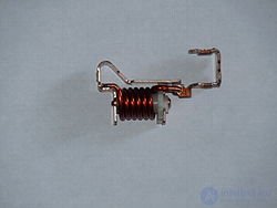
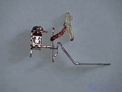
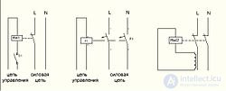
Releases (trip units) are electromagnetic, electronic, microprocessor-based, or thermal-bimetallic elements that serve to trip the circuit breaker via the free-tripping mechanism in the event of a short circuit, overload, or loss of voltage in the primary circuit (directly: electromagnetic and thermal-bimetallic elements; or indirectly through a separate independent electromagnetic release: electronic and microprocessor-based ones).
The free-tripping mechanism consists of levers, latches, rocker arms, and tripping springs, and is designed for instantaneous tripping of the circuit breaker (regardless of the position of the closing control: it is impossible to hold the circuit breaker in the closed position when the release operates), as well as to prevent re-closing of the circuit breaker onto a short circuit while a closing command continues to be present.
The instantaneous release is a solenoid (7), whose moving core can also actuate the tripping mechanism. The current flowing through the breaker passes through the solenoid winding and causes the core to be drawn in when a set current threshold is exceeded. Unlike a thermal release, the instantaneous release operates very quickly (fractions of a second), but at a significantly greater current overshoot: 2÷10 times the rated value, depending on the type (circuit breakers are divided into types (classes) A, B, C, and D depending on the sensitivity of the instantaneous release). In circuit breakers for large currents, starting in the 1970s electronic releases began to be used (for example, domestic circuit breakers of the «Elektron» series, some types of breakers of the A-37 and VA series), and more recently, microprocessor-based releases (microprocessor-based protection units) .
It is a bimetallic strip (5) that is heated by the current flowing through it. When the current exceeds the permissible value, the bimetallic strip bends and activates the tripping mechanism. The tripping time depends on the current (the time-current characteristic) and can range from seconds to an hour. The minimum current at which the thermal release must trip is 1.45 times the setting current of the thermal release. The trip current is adjusted during manufacture using an adjusting screw (6). Unlike a fuse, a circuit breaker is ready for reuse once the strip has cooled down. The role of the thermal release can be performed by an electromagnetic (instantaneous) release equipped with a hydraulic time-delay mechanism. Such circuit breakers are notable for their fire safety, since they have no heated element (bimetallic strip).
A bimetallic strip is a band made of two metal strips with different coefficients of thermal expansion. In a circuit breaker it acts as the thermal release. The two strips are not fused together and are usually joined at one end by soldering or welding. The other ends are fixed in place. The bimetallic strip is connected in the circuit in series with the load. As it is heated by the electric current, the strip bends toward the metal with the lower coefficient of linear expansion. In the event of an overload, the bending of the strip causes the circuit breaker to trip .
Normal and selective circuit breakers do not have a current-limiting action. High-speed breakers, like fuses, do have a current-limiting action, since they interrupt the circuit before the current in it reaches the value Ip.
Selective circuit breakers make it possible to implement selective protection of networks by installing circuit breakers with different time delays: the shortest at the load end, increasing in steps toward the power source.
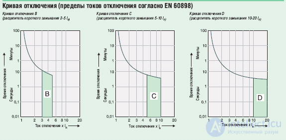
Trip diagram of modular circuit breakers from various manufacturers (the region of instantaneous trip currents is shaded)
According to GOST R 50345-2010 (clause 5.3.5), household AC circuit breakers are divided into the following types (classes) by instantaneous trip current:
Industrial circuit breakers can be of the following types:
European manufacturers' classifications may differ somewhat. In particular, there is an additional type A (over 2·In up to 3·In).
ABB has circuit breakers with curves K (8 — 14·In) and Z (2 — 4·In), which comply with IEC 60947-2.
The characteristics of breakers are checked in the course of type tests (durability of markings; reliability of screws, current-carrying parts and connections; reliability of terminals for external conductors; protection against electric shock; electrical insulation arrangements; temperature rise (28-day test); interruption characteristic; mechanical and electrical (switching) endurance; short circuit; resistance to mechanical shocks and impacts; heat resistance; resistance to abnormal heat and fire; corrosion resistance).
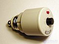
Circuit breaker in a plug-fuse-style enclosure
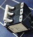
3-pole protective circuit breaker for direct mounting
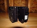
Circuit breakers used in the USA
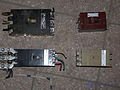
Circuit breakers of Soviet manufacture
1
2
2
3
4
5
6
7
8
9
|
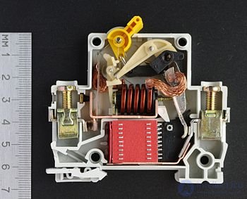
A circuit breaker rated for small currents nowadays most often has a modular design intended for mounting on a DIN rail. The internal construction of a modular circuit breaker is shown in the figure on the right. Switching on and off is done with the lever (1); the wires are connected to the screw terminals (2). The latch (9) secures the breaker's housing on the DIN rail and, if necessary, allows it to be easily removed (to do this, the latch must be pulled back by inserting a flat screwdriver into the latch's loop). Circuit switching is performed by the movable (3) and fixed (4) contacts. The movable contact is spring-loaded; the spring provides the contact pressure force in the on state and ensures their rapid opening when the tripping mechanism's pawl is released via one of two releases: thermal (5) or electromagnetic (7). An electric arc may occur while the contacts are opening, so the contacts have a special shape and are located next to the arc-quenching grid (8).
A voltage monitoring relay is a device that prevents the occurrence of overvoltage or undervoltage, protecting the devices on that network. The operating principle of this device is to prevent overload of electrical appliances.
A load-break switch — a high-voltage (or low-voltage) switching device which, in terms of permissible switching currents, occupies an intermediate position between a disconnector (switching under load is prohibited (as an exception, switching on the no-load current of transformers and lines is permitted — see Disconnector for details)) and a circuit breaker (oil, vacuum, air, electromagnetic, SF6) that is capable of interrupting, without damage, both rated load currents and overcurrents under fault conditions. A load-break switch permits switching of the rated current, but is not designed to break currents during a short circuit. Interruption of overcurrents in such switches is carried out by special fuses.
The drive of load-break switches can be a manual type with direct closing and opening from a pre-tensioned spring. Sometimes an electric drive for closing is used (for example in the VVNR «Volna») as well as a solenoid for remote opening.
By the method of arc extinguishing, load-break switches are divided into:
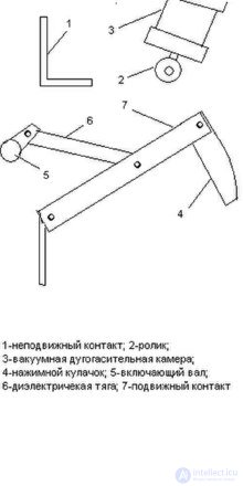
Vacuum load-break switch
This is a device that allows a circuit under load to be quickly closed or opened. A load-break switch is not the same as a circuit breaker, since it has no automatic tripping system. However, load-break switches have reinforced contacts whose service life far exceeds that of the contacts of ordinary breakers. This is necessary in order to be able to safely de-energize a line that is under load. If a load is switched off with an ordinary circuit breaker, the arc that forms when the circuit is broken can eventually cause the contacts to weld together. Therefore, ordinary breakers cannot be used for switching a load on and off. They are needed to protect the wiring in the event of an abnormal situation arising in the power supply circuit they protect.
Some models of load-break switches also have double contact break, which guarantees complete de-energization of the disconnected line.
In order to be able to visually confirm that the contacts of the mini knife switch have opened, some models have a special viewing window. Through it you can see the state (closed or open) of the switch's contacts.
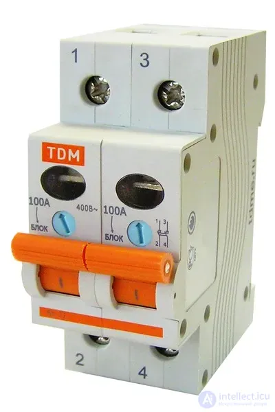
They come in 1, 2, 3 and 4-pole versions. The choice depends on whether your network is single-phase or three-phase and whether the neutral needs to be broken by the switch. Such load-break switches are mounted on a standard DIN rail. This is very convenient, since they can be installed in any distribution panel.
By current rating, mini knife switches are classified in the same way as circuit breakers. That is, 16, 20, 25, 32, 40, 63, 80, 100, 125A.
Load-break switches are installed in switchgear and substations of 6-10 kV and allow switching of up to several MVA, depending on the design and rated current.
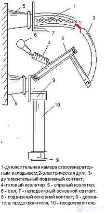
As additional elements, a load-break switch may be fitted with manually operated earthing blades (in which case mechanical mutual interlocking of the earthing blades and the load-break switch's power contacts is usually provided), a remote tripping solenoid, and signal contacts indicating the position of the switch contacts and fuse operation.
Not to be confused with a circuit breaker.
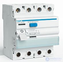
Residual current device (RCD) , (English: residual current device, RCD) - a mechanical switching device intended to make, carry and break electric currents under normal operating conditions and to open the contacts when the residual current reaches a specified value under specified conditions. Used as an RCD are a circuit breaker controlled by residual current without built-in overcurrent protection (RCCB) and a circuit breaker controlled by residual current with built-in overcurrent protection (RCBO).
Difference between an RCCB and an RCBO: an RCCB trips on a leakage current that must not exceed 30 mA for personal protection and 0.5 A for fire protection; an RCBO protects not only against leakage, it also provides reliable protection against overloads and short circuits in the mains network
RCDs with a rated residual operating current not exceeding 30 mA are intended for additional protection of persons against electric shock. Used as part of «automatic disconnection of supply» protection .
In AC systems, additional protection by means of an RCD must be provided for:
The RCD disconnects the protected circuit:
Requirements for the installation and use of RCDs are given in the IEC 60364 series of standards for building electrical installations.
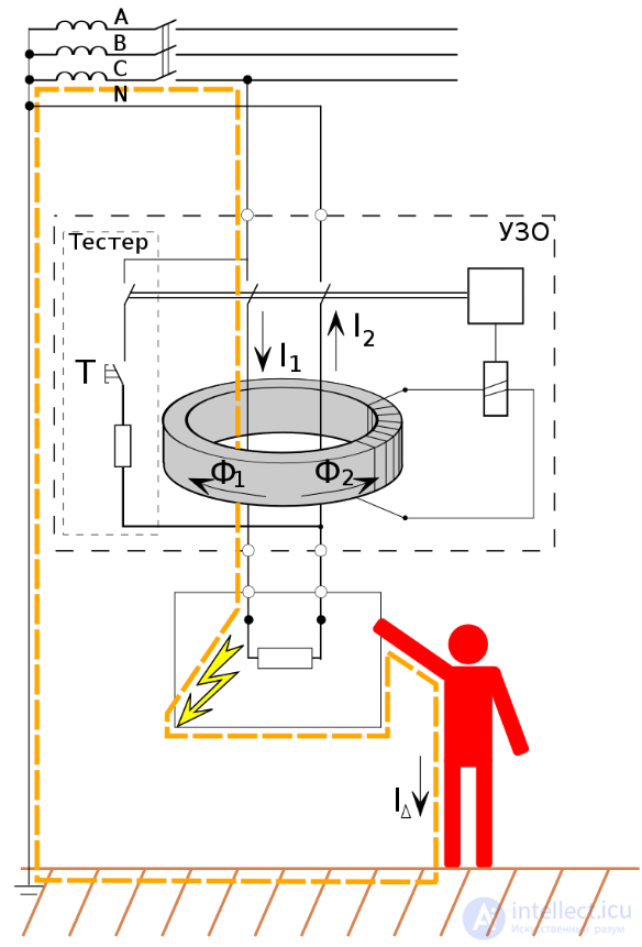
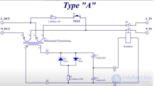
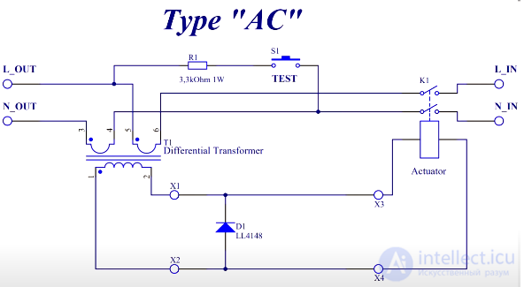
The main component of an RCD is a differential (residual current) transformer, designed to detect the residual current. If the residual current exceeds or equals the rated residual operating current, the electrical circuit will be opened.
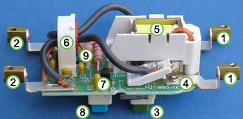
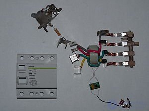
The photograph shows the internal construction of one type of RCD. This RCD is designed to be installed in-line with the wire. The line and neutral conductors from the power source are connected to terminals (1), and the RCD's main circuit is connected to terminals (2).
When the button (3) is pressed, the contacts (4) (as well as another contact hidden behind assembly (5)) close, and the RCD allows current to flow. The solenoid (5) holds the contacts in the closed position after the button is released.
The secondary winding (6), to which the residual-current release is connected. Under normal conditions the current in the line conductor equals the current in the neutral conductor, but these currents are opposite in direction. Thus, the currents cancel each other out and no EMF is induced in the coil of the differential (toroidal) transformer.
A ground fault current disrupts the balance in the differential transformer: a larger current flows through the line conductor than through the neutral conductor (part of the current flows through the person's body, i.e. bypassing the transformer). The residual current in the primary winding of the differential transformer causes an EMF to appear in the secondary winding. This EMF is immediately detected by the sensing device (7), which cuts off power to the solenoid (5). The de-energized solenoid no longer holds the contacts (4) closed, and they open under the force of the spring.
The device is designed so that tripping occurs within a fraction of a second, which greatly reduces the severity of the consequences of electric shock.
The test button (8) makes it possible to check that the device is working by passing a small current through the orange test wire (9). The test wire passes through the core of the differential transformer, so the current in the test wire is equivalent to an imbalance of the current-carrying conductors, i.e. the RCD should trip when the test button is pressed. If the RCD does not trip, it is faulty and must be replaced.
The RCD will not trip if a person comes under voltage but no ground fault current arises, for example when simultaneously touching both the line and neutral conductors of the protected circuit. It is impossible to provide protection against such contact, since there is no way to distinguish current flowing through a person's body from the normal flow of current in the load. In such cases only mechanical protective measures are effective (insulation, non-conductive enclosures, etc.), as well as switching off the electrical installation before servicing it.
An RCD whose operation depends on the mains voltage needs a power supply, which it draws from the protected circuit. This makes it potentially dangerous when a break occurs in the neutral conductor upstream of the RCD while the line conductor remains live. In this case the RCD will be unable to disconnect the circuit, since the voltage in the protected circuit is insufficient for it to operate. An RCD whose operation does not depend on the mains voltage is free of this drawback.
The first patent (German patent No. 552678 of 08.04.28) for an RCD was obtained in 1928 by the German company RWE (Rheinisch — Westfälisches Elektrizitätswerk AG). The first working prototype of the protective device was produced by the same company in 1937. A small differential transformer was used as the sensor, and a polarized relay with a sensitivity of 0.01 amperes and a response time of 0.1 s served as the actuating element.
The sensitivity of the prototype device was 80 mA – further increases in sensitivity were held back by the lack of materials with the required magnetic properties. In 1958, Dr. Biegelmeier of Austria proposed a new circuit design for the RCD. Such RCDs are now marked with the letter G. In this design, false tripping caused by lightning discharges was eliminated and the sensitivity was increased to 30 mA.
The boundary curves of alternating current and the physiological effect of current on the human body were established through tests in 1940—1950 at the University of California, Berkeley by the American scientist Charles Dalziel. During the tests, volunteers were exposed to electric current with a known voltage and current magnitude.
In the early 1970s, most RCDs were produced in circuit-breaker-type enclosures. Starting in the early 1980s, in the USA most residential RCDs were already built into outlets.
In the USSR, the first experiments in RCD design began in 1964. The first production RCD for equipping three-phase electrified tools was manufactured in 1966 by the Vyborg «Elektroinstrument» plant, based on a design by VNIISMI. The first residential RCD in the USSR was developed in 1974, but was not put into series production. Series production of residential RCDs began in 1988 in significant quantities (up to 200 thousand units per year). A typical RCD of that time was an extension cord with a socket on the cord. From 1982, all educational electrical equipment supplied to schools was mandatorily fitted with an RCD, which received the name «school type». Production volume reached up to 60 thousand units per year. For the needs of industry and agriculture, protective devices IE-9801, IE-9813, UZOSh 10.2 (still in production), and RUD-0.5 were manufactured.
Nowadays, RCDs intended for DIN-rail mounting in a distribution board are predominantly used, while built-in RCDs have not yet become widespread.
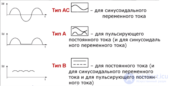
Type AC RCD: an RCD whose tripping is ensured by a differential sinusoidal alternating current, whether suddenly applied or slowly rising .
Type A RCD: an RCD whose tripping is ensured both by sinusoidal alternating and by pulsating direct differential current, whether suddenly applied or slowly rising .
Type B RCD: an RCD that guarantees tripping like a type A device and additionally trips:
RCD Type F: an RCD that guarantees tripping as a Type A device in accordance with the requirements of IEC 61008-1 and IEC 61009-1, and additionally trips:
For a simple test of different types of RCBOs, the so-called battery test can be used

Comments