
Lecture 10 min.
A dimmer (from English dim «to darken»), also called a light regulator, is an electronic device designed to change electrical power (a power regulator). It is usually used to adjust the brightness of light emitted by incandescent lamps or LEDs.
The simplest dimmer is a variable resistor (for example, a rheostat), but such a regulator dissipates an excessively large amount of power, comparable at low brightness levels to the power of the load, which causes low efficiency and strong heating of the device. An autotransformer can also serve as a dimmer. Compared with triac and thyristor dimmers, autotransformers are larger and heavier, require greater mechanical effort to operate, and are more expensive, but they produce an undistorted sinusoidal (or very close to it) output signal at a frequency of 50 or 60 Hz over the entire range of regulated voltage, without introducing switching noise.
Electronic dimmers are considered the most compact and economical. In all modern electronic dimmers, a semiconductor triac or transistor switch is used as the power element. It is important to remember that most electronic dimmers do not output a sinusoidal signal, but rather sections of a sine wave cut off by the electronic switch. Devices that require power from a current with a low harmonic distortion factor (including electric motors, induction transformers for halogen lamps, etc.) must not be connected to such dimmers: this can lead to device failure due to overheating of the winding. Also, cheap electronic dimmers not equipped with a special filter can generate strong electromagnetic interference.
The first dimmers had a mechanical control method and could perform only one function — changing the brightness of the light fixture. Modern multifunctional light regulators are equipped with a microcontroller and have an extended set of functions:
There are also signal-type dimmers, for example, dimmers with a 0-10V output interface. Such dimmers send commands to external controllers, electronic ballasts (EB), and other devices, which in turn regulate the luminous flux, motor speed, sound level, etc.
Various types of dimmers are shown in the figures.
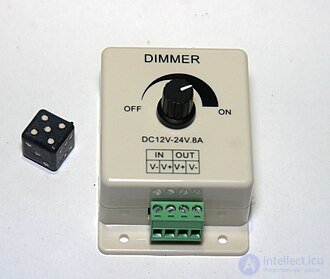
A dimmer for controlling the brightness of LEDs and 12 V incandescent lamps up to 96 W, with pulse duty cycle regulation by a potentiometer
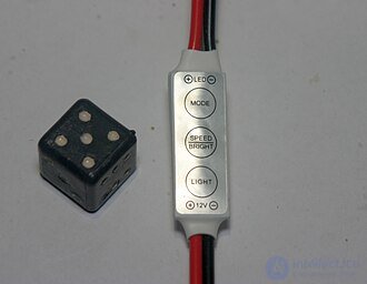
A miniature dimmer for LEDs and 12 V incandescent lamps up to 24 W, with pushbutton control
| Criterion | Classic dimmer (TRIAC/phase-cutting) | PWM dimmer (PWM) |
|---|---|---|
| Operating principle | Cuts off part of the AC sine wave (leading or trailing edge) | Supplies power in DC pulses, varying the pulse width |
| Signal type | analog, based on changing the shape of the voltage | digital, based on pulse-width modulation |
| Compatibility | Works well with incandescent and halogen lamps | Optimal for LEDs and LED strips |
| Problems in use | Causes flicker, noise, and instability on LEDs | With correct selection, provides stable brightness without flicker |
| Efficiency | Higher energy losses, especially at low brightness | More energy-efficient, since it controls the on-time rather than reducing the voltage |
| Application | Domestic 220 V mains, classic lamps | LED strips, DC drivers, low-voltage systems |
Sources:
Rheostat-based dimmers were inefficient, as they dissipated a significant part of the load's rated power as heat. They were large and required a large amount of cooling air. Since the dimming effect depended largely on the total load applied to each rheostat, the load had to be selected quite carefully in accordance with the rheostat's rated power. Finally, since they relied on mechanical control, they were slow, and it was difficult to switch many channels simultaneously.
Early examples of rheostat dimmers include the saltwater-based dimmer, a kind of liquid rheostat; the liquid between the movable and fixed contacts provided variable resistance. The closer the contacts were to each other, the higher the voltage available for the lamp. Saltwater-based dimmers required regular addition of water and maintenance due to corrosion; the exposed parts were live during operation, presenting a risk of electric shock.
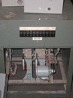
Two autotransformer dimmers, each rated at 6000 W, driven by electric motors, are used to light a theater auditorium.
The coil-rotation transformer used a fixed-position electromagnet coil combined with a variable-position coil to change the mains voltage by changing the orientation of the two coils. When rotated by 90 degrees, the secondary coil is exposed to two equal but oppositely directed fields from the primary coil, which effectively cancel each other out and produce no voltage in the secondary coil.
These coils resembled the standard rotor and stator used in an electric motor, except that the rotor was held from rotating by brakes and moved to specific positions by a high-torque gear drive. Since the rotor never made a full revolution, a commutator was not required, and long flexible cables could be used instead.
Then adjustable autotransformers (trade name « Variac ») were introduced. Although they are still almost as large as the rheostat dimmers they closely resemble, they are relatively efficient devices. Their output voltage, and consequently the dimming effect, is largely independent of the connected load, which greatly simplified the design of lighting fixtures connected to each channel of the autotransformer. Remote control of dimmers was still impractical, although some dimmers were fitted with motor drives that could slowly and smoothly decrease or increase the brightness of the connected lamps. Autotransformers have fallen out of use in lighting, but are used in other fields.
However, there are certain lighting scenarios in which autotransformers are still the preferred solution (as of 2021). For example, a recording studio's control room may require extremely strict limits on electromagnetic interference. Compared to solid-state dimmers, the conducted interference produced by autotransformers is practically zero.
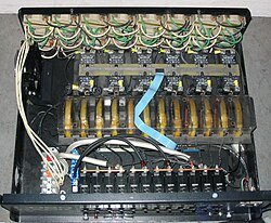
A rack of thyristor dimmers
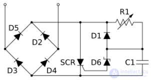
Electrical circuit of a typical thyristor-based dimmer.
To address some of these problems, solid-state dimmers were developed. Solid-state dimmers switch on at an adjustable time (phase angle) after the start of each half-cycle of alternating current, thereby altering the shape of the voltage supplied to the lamps and, consequently, changing its root-mean-square effective value. Since they switch rather than absorb part of the supplied voltage, energy losses are minimal. Brightness adjustment can be practically instantaneous and is easily controlled by remote electronics. This development also made it possible to build dimmers compact enough to be used in place of ordinary household light switches (inside the enclosure).
Switches release a certain amount of heat during switching and can also cause radio-frequency interference. [ 7 ] Inductors or chokes are used as part of the circuit to suppress this interference. When a dimmer operates at 50% power, the switches commutate the maximum voltage (>325 V in Europe), and the sudden power surge causes the inductor coils to move, producing a buzzing sound characteristic of some types of dimmers; the same effect can be heard in incandescent lamp filaments as «singing». The suppression circuit may prove insufficient to prevent buzzing on sensitive audio and radio equipment that uses the same mains supply as the lighting fixtures. In this case, special measures must be taken to prevent this interference. [ 8 ] European dimmers must comply with the requirements of the relevant electromagnetic compatibility legislation; this includes suppressing the emissions described above to the limits specified in EN55104.
In the circuit shown, a typical thyristor-based (SCR) dimmer controls the brightness of a light by phase control. This unit is connected in series with the load. Diodes D2, D3, D4 and D5 form a bridge that generates pulsating direct current. Resistor R1 and capacitor C1 form an RC time-constant network. As the voltage rises from zero (at the start of each half-cycle), capacitor C1 charges. When C1 is able to make zener diode D6 conduct and feed current into the thyristor, the thyristor fires. When the thyristor is conducting, diode D1 discharges capacitor C1 through the thyristor. The thyristor turns off when the current drops to zero and the supply voltage falls at the end of the half-cycle, preparing the circuit to operate in the next half-cycle. This circuit is called a leading-edge dimmer or forward-phase dimming .
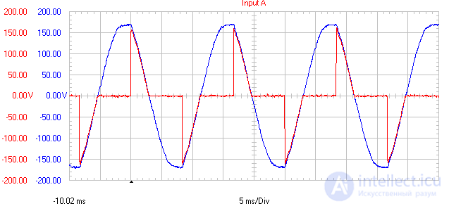
Graph of the output voltage of a thyristor dimmer set to 60 volts RMS, with an input voltage of 120 V. The red line shows the output device turning on approximately 5.5 ms after the input (blue) voltage crosses zero. Earlier triggering of the thyristor in each half-cycle results in a higher output voltage and brighter light.
Dimmers based on insulated-gate bipolar transistors (IGBTs) eliminate most of the noise present in thyristors by cutting off the trailing part of the sinusoidal signal. Such circuits are called reverse-phase dimmers or trailing-edge dimming .
An even newer, but still expensive, technology is sine-wave dimming , which is implemented using a powerful switch-mode power supply followed by a filter.
Dedicated fan speed controllers (triac- or thyristor-based circuits) — better adapted for motors.
Built-in controllers — many fans come with their own speed controllers.
Inverter (VFD) systems — a more expensive but efficient option for smooth control.
Dimmers are used:
Dimmers can be used with caution (since there is a risk of damaging the motor) to adjust the rotational speed of low-power electric motors.
Dimmers should not be used with radio receivers, televisions and other devices with transformer-based power supplies or switch-mode power supplies (including fluorescent lamps with electronic ballasts).
Dimmers are classified by their method of control:
A mechanical dimmer is based on a potentiometer that is not connected directly to the load but instead transmits a signal through a control circuit to a power element (rheostat, choke, thyristor).
In electronic dimmers, the following sensing methods are possible:
In remote dimmers, control is carried out by a remote control that emits infrared (IR) or radio (RF) waves.
An acoustic dimmer responds to a loud sound or to voice commands (see voice control).
A single device may use several control methods at the same time.
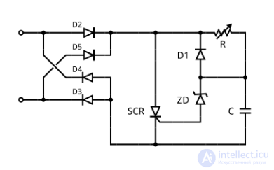
A simple modern dimmer:
D2…D5 — diode bridge.
ZD — diac.
D1 — diode.
R — low-power variable resistor.
C — capacitor.
SCR — thyristor, whose power rating determines the load power
At the initial moment the SCR thyristor is closed, and capacitor C charges through resistor R. The voltage of the input half-wave rises, and at a certain moment the diac ZD opens, followed by the SCR thyristor. A significant current begins to flow between the terminals. Current flows until the half-wave voltage drops enough for the diac ZD to close. At this point capacitor C discharges through diode D1 and the SCR thyristor. The thyristor closes. On the next cycle the process repeats.
The load is connected in series (in the figure the terminals are located on the left).
The operating principle of such a dimmer is that, by turning on the thyristor at different moments in time relative to the voltage zero-crossing, the sine waves of the regulated voltage can be «clipped», thereby changing the RMS value of the voltage and the current in the load.
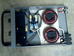
To suppress radio interference, high-power dimmers are often fitted with chokes
In most dimmers, switching circuits are used, the operation of which excites electromagnetic waves over a wide range of frequencies. These waves excite currents in the wires connecting the dimmer to the power source and to the controlled load, creating interference. To reduce interference, dimmer designs often incorporate chokes (inductors) (as a reactive element), as well as LC (inductive-capacitive) filters on both the supply side and the load side. The higher the frequency of the alternating current, the smaller the choke required, and combining this with good filter capacitors of low resistance makes it possible to achieve an acceptable level of interference. Modern dimmers no longer interfere with the operation of radio receivers.
Some companies (including the world leaders in the production of electrical installation products, Schneider Electric and Teco) already manufacture dimmers for fluorescent lamps. The functionality of the dimmers produced depends directly on the circuit design of the electronic ballast (EPRA).
Electrical equipment manufacturers Feller, Gira, Jung, Merten, and Schneider Electric, together with lamp manufacturers OSRAM and Radium, developed the open standard LEDOTRON ( ) in order to standardize dimmers and fluorescent or LED lamps.
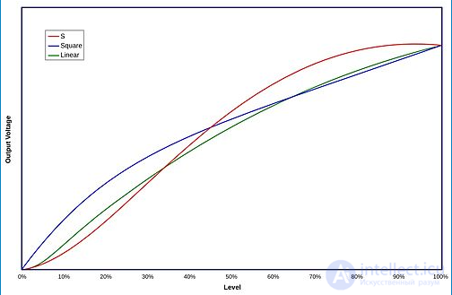
The design of most analog dimmers meant that the dimmer's output signal was not directly proportional to its input. Instead, as the operator raised the slider, the dimmer would first decrease brightness slowly, then rapidly in the middle, and then slowly again near the top. The shape of the curve resembled the third quarter of a sine wave. Different dimmers produced different brightness-adjustment curves, and different applications generally required different responses.
Television systems often use a «square-law» curve, which provides more precise control at the upper part of the curve, which is extremely important for precise adjustment of the color temperature of the lighting. Theatrical dimmers generally use a softer S-shaped or linear curve. Digital dimmers can have any curve set by the manufacturer; they may offer a choice between a linear response and a set of different curves, which allows them to be matched to older analog dimmers. Sophisticated systems provide user-programmable or custom curves, and one common use of a custom curve is to turn the dimmer into a «non-dimmer» that switches on at a user-defined control level.
Switching high-power incandescent lamps (with a filament) to full power from a cold state can significantly shorten their service life due to the large inrush current. To reduce the stress on the filaments, dimmers may have a preheat function. It sets a minimum level, typically from 5% to 10%, which looks off but prevents the lamp from cooling excessively. This also speeds up the lamp's response to sudden power jumps, which is highly valued by operators of rock-and-roll shows. The opposite of this function is sometimes called a «maximum setting». It limits the maximum power supplied to the lamp, which can also extend its service life.
In less sophisticated systems, the same effect is achieved by preheating (warming up) the lamps before an event or performance. This is usually done by gradually increasing the lighting power to full (or, typically, to 90-95%) over the course of half an hour or an hour. This is just as effective as a built-in preheat function.
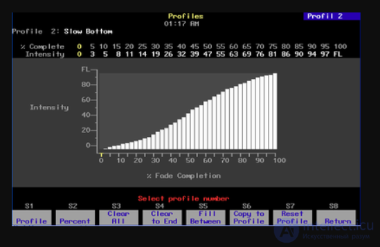
An example of an S-shaped curve that can be used to create smooth transitions on a lighting board.
Modern digital control consoles can emulate preheat and dimming curves, and also allow programmed settings to be created in memory. This is often preferable, since it allows a dimmer rack to be replaced with another one without having to transfer complex settings. Many different curves or profiles can be programmed and used on different channels.
One of the quality indicators of a leading-edge dimmer is the «rise time». In this context, rise time is the time required for the chopped signal to go from zero to the instantaneous output voltage. On the graph shown above, this is indicated by the slope of the nearly vertical edge of the red line. It is usually measured in tens or hundreds of microseconds. A longer rise time reduces dimmer and lamp noise, and also extends the lamp's service life. A longer rise time also reduces the electromagnetic interference generated by the dimmer. Unsurprisingly, implementing a longer rise time is more expensive than a shorter one, since the size of the choke has to be increased. New dimming methods can help minimize such problems.
| Regulation method | Compatibility | Pros | Cons |
|---|---|---|---|
| Dimmer | Only compatible motors | Simplicity, low cost | Noise, risk of overheating |
| Triac regulator | Most induction motors | Reliability, smoothness | Requires installation |
| Factory-fitted controller | Specific fan model | Safety, warranty | Limited versatility |
| Inverter | Any motors | Maximum efficiency | High price |

Comments