
Lecture
The calculation of electrical circuits with sinusoidal alternating current is carried out in complex form. In this case, the values of sinusoidal EMFs and currents are represented as complex amplitudes or complex rms values, and all elements in the circuit – as complex impedances.
For example, if the source EMF equals 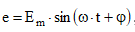 , then the complex amplitude is written as
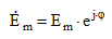 - in exponential form, or
 - in algebraic form. The complex rms value of the sinusoidal EMF:
 - in exponential form, or
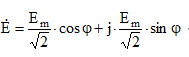 - in algebraic form.
Complex impedances of the elements of an AC electrical circuit:
 - for an ideal resistance,
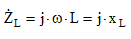 - for an ideal inductance,
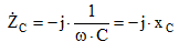 - for an ideal capacitance.
Further calculation of the AC electrical circuit can be carried out by any method known from the section – «DC electrical circuits». In this case, the mathematical apparatus developed for operations with complex numbers is used.
Three forms of writing the complex value of a sinusoidal quantity are used:
 - exponential form,
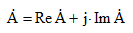 - algebraic form,
where  - the real and imaginary part of the complex value of the sinusoidal quantity. The transition from algebraic form to exponential form is carried out by the formulas:
 .
.
The transition from exponential form to trigonometric form is carried out by Euler's formula:
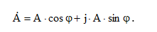 .
.
Addition and subtraction of complex quantities is carried out in algebraic form, and multiplication and division in exponential form.
In the analysis of sinusoidal current circuits, mainly the complex rms values of sinusoidal quantities are used; for short, they are called complex values.
The calculation of single-phase AC circuits with a single source of sinusoidal EMF is carried out by the method of equivalent transformations. Let us consider an example of calculating a single-phase circuit shown in the figure.
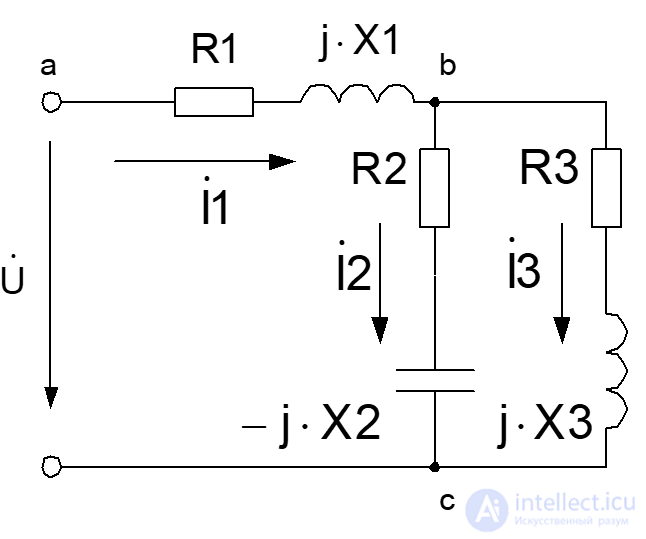
Fig. 2.4. Diagram of the electrical circuit for the calculation example
Example of calculating a single-phase circuit
Given the values of the active and reactive resistances and the source voltage, determine the currents in all branches of the circuit and the voltage drops across its sections. Determine the complex apparent power, the active and reactive power. Perform the calculation using the complex method. Verify the correctness of the calculation using the active power balance of the circuit. Construct a vector diagram. Construct the instantaneous values of the sinusoidal branch currents. The initial data for the calculation are given in the table.
|
U, V |
R1, Ω |
R2, Ω |
R3, Ω |
X1, Ω |
X2, Ω |
X3, Ω |
|
100 |
50 |
100 |
100 |
50 |
50 |
100 |
Solution:
The electrical circuit in Fig. 2.4 consists of three branches; let us determine the complex impedances of the branches. The impedance of the first branch, consisting of resistance R1 and an ideal inductor with complex impedance :
:
 Ω.
Ω.
The impedance of the second branch, consisting of resistance R2 and an ideal capacitance with complex impedance :
:
 Ω.
Ω.
The impedance of the third branch, consisting of resistance R3 and an ideal inductor with complex impedance :
:
 Ω.
Ω.
The second and third branches are connected in parallel, so their equivalent impedance

The equivalent impedance of the entire circuit:
 Ω.
Ω.
Knowing the equivalent resistance, we can determine the current in the first branch:
 A.
A.
Next, the voltages across the sections of the circuit can be determined:
 V,
V,
 V.
V.
Knowing the voltage across section bc, the currents can be calculated
 A,
A,
 A.
A.
The correctness of the current calculation can be verified using Kirchhoff's first law in complex form:
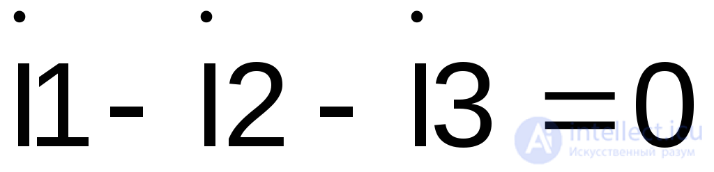 , or
, or
 .
.
Since Kirchhoff's first law is satisfied, the current calculation is correct.
Complex power:
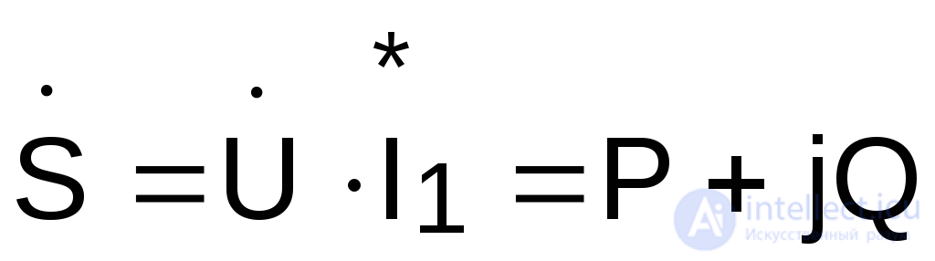 ,
,
where  - is the conjugate complex of the current
 . If
. If A, then the conjugate complex is
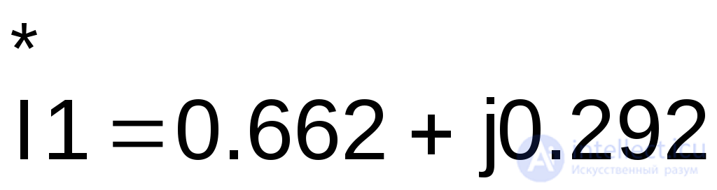 A. Thus, the complex power equals
 VA.
VA.
The real part of the complex power equals the active power consumed by the circuit
 W,
W,
and the imaginary part of the complex power equals the reactive power of the circuit
 VA.
VA.
The vector diagram of currents and voltages is constructed on the complex plane using the coordinates obtained from the calculation in complex form. Currents and voltages are plotted on the same coordinate axes, but different scales are chosen for them. The diagram for the calculated circuit is shown in Fig. 2.5.
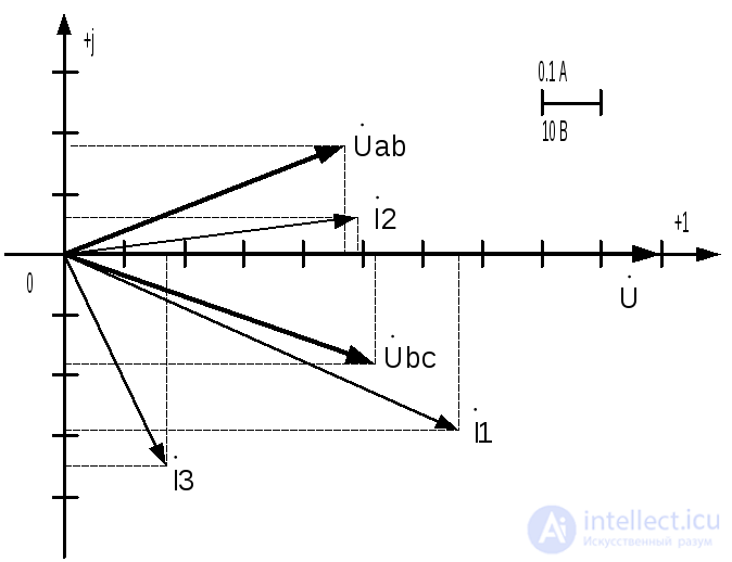
Fig. 2.5. Vector diagram of currents and voltages
Expressions for the instantaneous values of the currents can be obtained from the complex values written in exponential form:
 A.
A.
The RMS value of the current I1 = 0.724 A, and the phase shift , thus the instantaneous value of the current equals
 A.
A.
Similarly for the remaining currents:
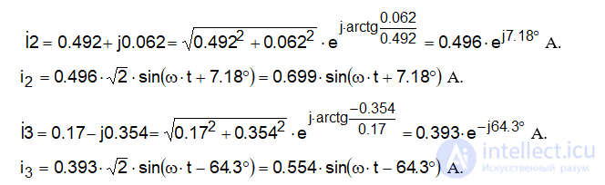
Graphs of the instantaneous values of the currents are shown in Fig. 2.6.
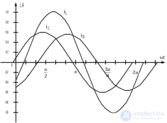
Fig. 2.6. Instantaneous values of the currents
The calculation of three-phase, three-wire electrical circuits under unbalanced conditions is performed by the complex method, since under these conditions the phase currents and voltages are not equal to one another and the basic relationships between line and phase quantities do not hold.
Example of calculating a three-phase circuit with a wye (star)-connected load:
A three-phase, three-wire circuit (Fig. 2.7) is given, with the load connected in wye, and the phase impedances of the load:

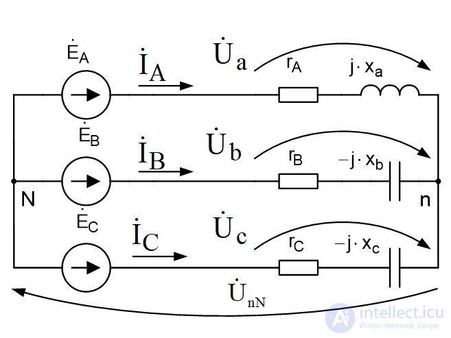
Fig. 2.7. Three-phase circuit with a wye-connected load
The load is unbalanced, and the EMFs of the ideal three-phase source are: 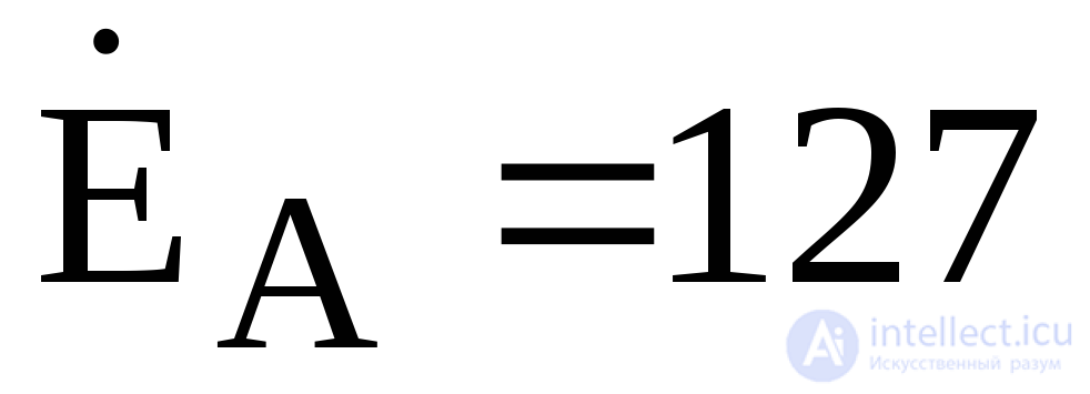 V,
V,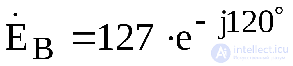 ,
, V.
V.
Given the values of the active and reactive resistances of the load phases, determine: the phase currents and voltages across the load, the neutral-point displacement voltage, and the active, reactive, and apparent power.
Solution:
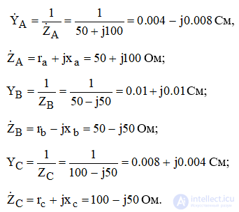
In the unbalanced operating mode of a three-wire three-phase circuit with a wye-connected load, a neutral-point displacement voltage  arises. The magnitude of this voltage can be determined by the two-node method. Given the known complex impedances and admittances of the load phases:
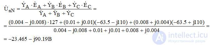
The neutral-point displacement voltage is determined by the formula:
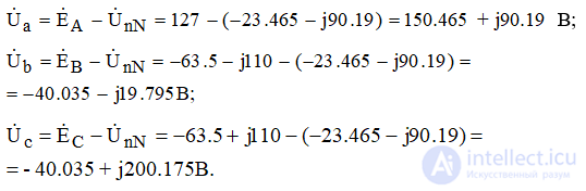
The phase voltages across the load under unbalanced conditions are determined by Kirchhoff's second law:
The phase currents of the load are equal to the line currents and are determined by the formulas:
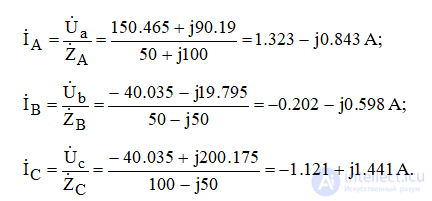
The sum of the phase currents, by Kirchhoff's first law, must equal zero:
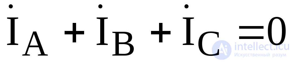 .
.
The complex apparent power of the wye-connected three-phase load:
 where:
 - are the conjugate complexes of the phase currents.
The active power P = 476.426 W, and the reactive power Q = 59.553 VA.
Example of calculating a three-phase circuit with a delta-connected load:
A three-phase, three-wire circuit is given (Fig. 2.8), with the load connected in delta and the load phase impedances:

The load is unbalanced; the EMFs of the ideal three-phase source are equal to: 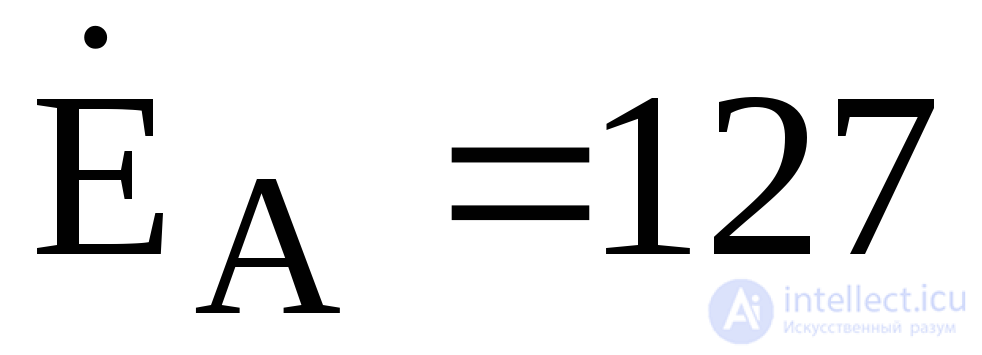 V,
V,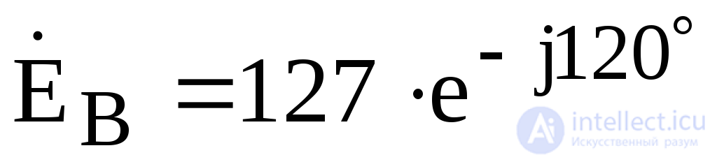 ,
, V.
V.
Using the given values of the active and reactive resistances of the load phases, determine: the phase currents and voltages across the load, the phase voltages across the load, the active, reactive, and apparent power.
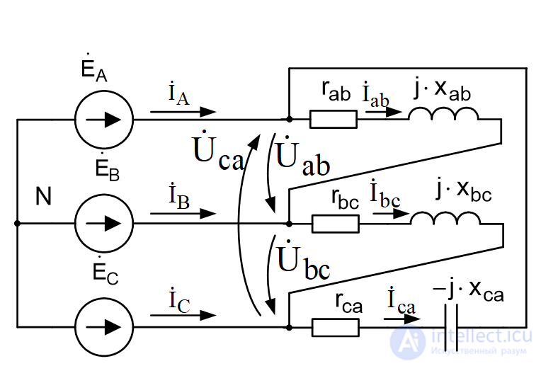
Fig. 2.8. Diagram of a three-phase circuit with the load connected in delta
Solution:
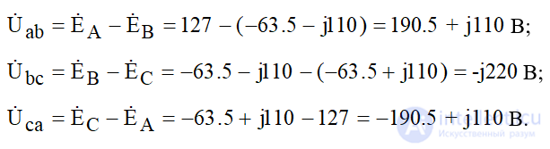
In the unbalanced operating mode of a three-wire three-phase circuit with a load connected in delta, the phase voltages across the load are equal to the line voltages of the power source. The magnitudes of these voltages can be determined using Kirchhoff's second law:
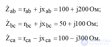
With the complex impedances of the load phases known:
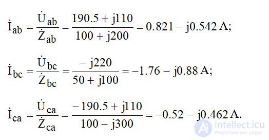
The phase currents are calculated using Ohm's law:
The line currents are determined using Kirchhoff's first law:
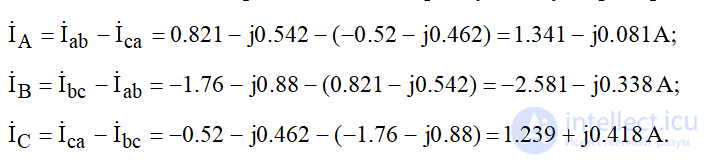
The sum of the line currents, by Kirchhoff's first law, must equal zero: 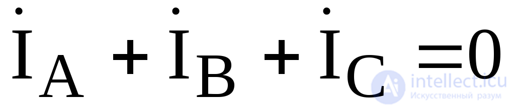 .
.
The complex apparent power of the three-phase load connected in delta:
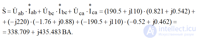
where: 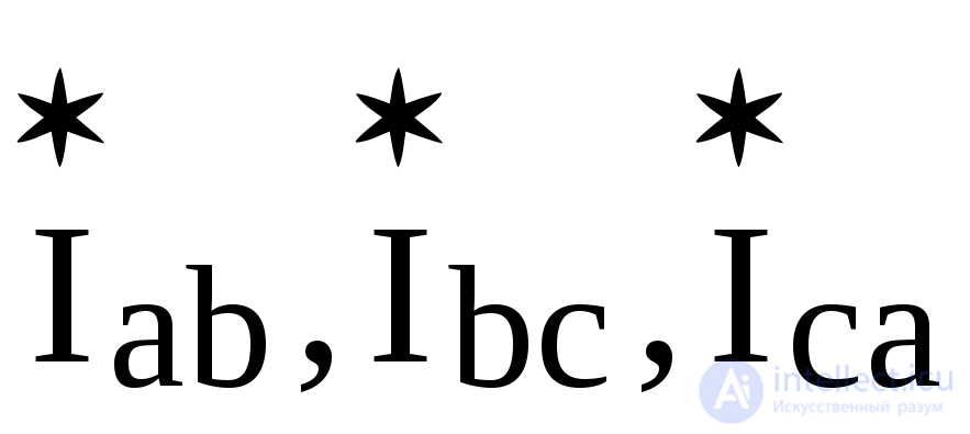 - are the conjugate complexes of the phase currents.
The active power P = 338.709 W, and the reactive power Q = 435.483 VA.

Comments