
Lecture
Servo systems (servo motors and servo drives) are widely used in modern industry, which is characterized by a high level of automation. These devices are used in many sectors where it is important to ensure highly stable or precise control.
Servo motors and servo drives are used in systems where maintaining speed, positioning industrial robotic systems, and high-precision machine tool equipment are important. These devices are mainly installed on the production lines of enterprises in the textile, woodworking, and printing industries; moreover, they are applicable in control systems for hoisting and conveying equipment, on packaging lines, etc.
On an electrical diagram, a servo drive is usually denoted not by a single special symbol, but as an assembly:
1. Servo motor
Denoted like an ordinary electric motor: M1 or SM1 / Servo Motor
Graphically — a circle with the letter M inside:
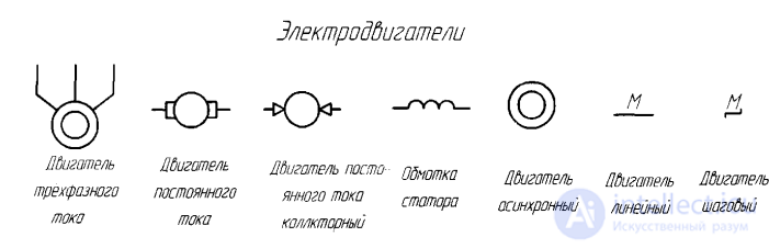
According to GOST/ESKD, the letter code M / D refers to electric motors.
GOST 2.722 establishes the graphical symbols specifically for rotating electrical machines.
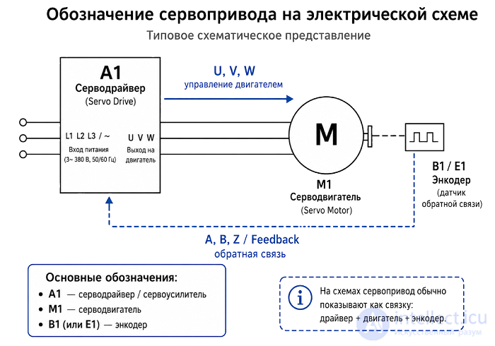
2. Servo amplifier / servo controller / drive
Usually shown as a rectangular block:
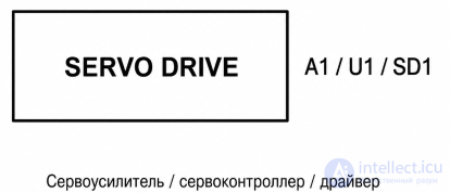
Labeled as:
3. Encoder / feedback sensor
Often denoted as a separate block:
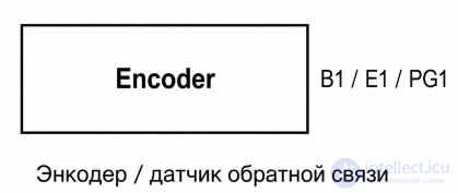
In IEC practice, a rectangular block with terminals and signals A, B, Z is often used for encoders, because a separate universal IEC symbol for a servo motor encoder is usually not defined.
IEC practice, International Electrotechnical Commission — is a way of drawing up electrical diagrams according to international IEC standards.
IEC practice — is a general approach to notation and diagram layout. Designations may differ slightly between different companies and countries. For example, an encoder might be labeled as B1, E1, PG1, ENC1.
A typical notation scheme for a servo drive and servo motor system:
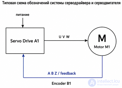

In practice, it is most often written as follows:
For a simple educational diagram, it is enough to denote the servo drive as:
U , V, W — are the three output phases from the servo drive to the servo motor. That is: Servo Drive A1 ── U V W ──► Motor M1
These are usually the power wires through which the drive supplies controlled three-phase voltage/current to the motor.
Roughly like in a three-phase motor:
U — first phase of the motor
V — second phase of the motor
W — third phase of the motor
A, B, Z — are the encoder signals, that is, feedback from the motor to the drive. Encoder B1 ── A B Z / feedback ──► Servo Drive A1
Usually:
A — encoder pulse channel A
B — encoder pulse channel B
Z — zero / index pulse
Channel A and channel B are phase-shifted relative to each other. From them the drive determines:
rotation speed
direction of rotation
shaft position
Channel Z usually gives one pulse per revolution and is needed as a marker of the zero/reference position.
And if you need to show the entire servo drive as a single functional unit:
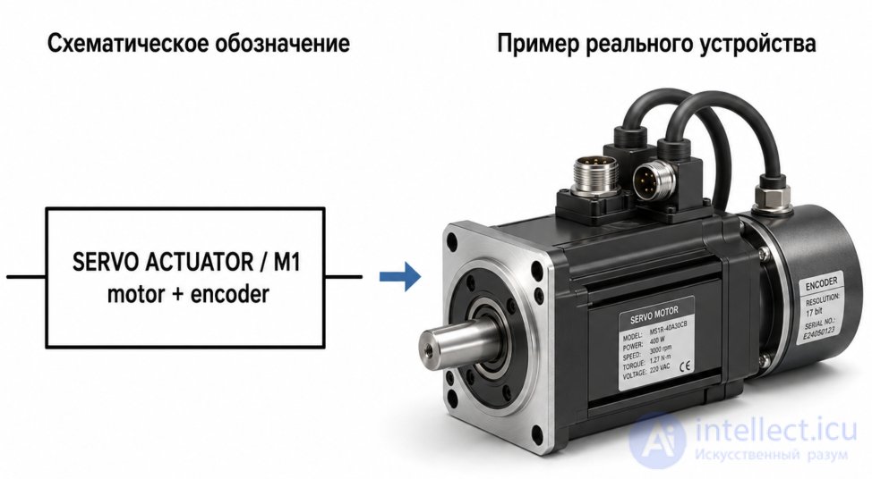
A servo drive gives the user the ability to fully control dynamic, high-precision processes over a wide speed range and ensures excellent repeatability. Servo drives are designed to track speed, torque and position with the accuracy and dynamics specified by the user. The classic design of a servo system consists of a motor, a position sensor and a control system, with three-loop control (position, speed, current).
Servo drive (from Latin servus — servant, helper, slave), or tracking drive — a mechanical drive with automatic state correction through internal negative feedback, in accordance with externally set parameters.
A servo drive is any type of mechanical drive (device, working member) that includes a sensor (of position, speed, force, etc.) and a drive control unit (an electronic circuit or a mechanical linkage system) that automatically maintains the required parameters at the sensor (and, accordingly, at the device) in accordance with a given external value (the position of a control knob or a numerical value from other systems).
In simpler terms, a servo drive is an «automatic precision executor» — receiving the value of a control parameter at its input (in real time), it strives, «on its own» (based on the sensor readings), to create and maintain this value at the output of the actuating element.
Many different regulators and amplifiers with negative feedback belong to the category of servo drives, for example, hydraulic, electric and pneumatic boosters for the manual actuation of control elements (in particular, steering and braking systems on tractors and automobiles); however, the term «servo drive» is most often used (and is used in this article) to denote an electric drive with position feedback, used in automatic systems for driving control elements and working members.
Servo drives are currently used in high-performance equipment in the following industries: mechanical engineering; automatic production lines for: beverages, packaging, building materials, electronics, etc.; material-handling equipment; printing; woodworking; food industry.
The simplest control unit of an electric servo drive can be built on a circuit that compares the feedback sensor value with the set value, applying voltage of the corresponding polarity (through a relay) to the electric motor. More complex circuits (based on microprocessors) can take into account the inertia of the driven element and implement smooth acceleration and deceleration of the motor to reduce dynamic loads and achieve more accurate positioning (for example, head actuation in modern hard disk drives).
Special CNC controllers can be used to control servo drives or groups of servo drives; these can be built on the basis of programmable logic controllers (PLCs).
Motor power: from 0,05 to 15 kW.
Torques (rated): from 0,15 to 50 N·m.
Another option for precise positioning of driven elements without a feedback sensor is the use of a stepper motor. In this case, the control circuit counts the required number of pulses (steps) from the reference position (this feature is responsible for the characteristic noise of a stepper motor in 3.5" floppy drives and CD/DVD drives during repeated read attempts). Precise positioning is here ensured by parametric systems with negative feedback, formed by the interaction of the corresponding poles of the stator and rotor of the stepper motor. The stepper motor control system, by activating the corresponding stator pole, generates a reference signal for the corresponding parametric system.
Since a sensor usually monitors the driven element, an electric servo drive has the following advantages over a stepper motor:
Disadvantages compared to a stepper motor
However, it is possible to use a servo drive based on a stepper motor, or in addition to it, to some extent combining their advantages and eliminating competition between them (the servo drive performs coarse positioning into the operating zone of the corresponding parametric system of the stepper motor, while the latter performs final positioning with a relatively large torque and position holding).
P.S.:
There is no positioning-lock problem at all in a servo drive, unlike in a stepper drive. High-precision positioning and holding at a set position is provided by operating the electric machine in vector (field-oriented) mode, the essence of which comes down to its operating as a force source. Depending on the position error (and other drive coordinates), a force command is generated. An undeniable advantage of a servo drive here is its energy efficiency: current is supplied only in the amount necessary to hold the working member in the set position. This is in contrast to stepper mode, in which the maximum current value is applied, which determines the machine's torque-angle characteristic. At small deflections, the machine's torque-angle characteristic is analogous to a mechanical spring that tries to «pull» the working member to the required point. In a stepper drive, the greater the position error, the greater the force, at a constant current.
1. Rotary-motion servo drive
2. Linear-motion servo drive
Synchronous servo drive — allows precise setting of the rotation angle (to an accuracy of arc-minutes), rotational speed, and acceleration. It accelerates faster than an asynchronous one, but is many times more expensive.
Asynchronous (induction) servo drive (an induction machine with a speed sensor) — allows precise setting of speed, even at low rpm.
Linear motors — can develop enormous accelerations (up to 70 m/s²).
3. By operating principle
In an electromechanical servo drive, motion is generated by an electric motor and a gearbox.
In an electrohydromechanical servo drive, motion is generated by a piston-cylinder system. These servo drives have a response speed an order of magnitude higher compared to electromechanical ones.
Servo drives are used for precise (sensor-based) positioning (most often) of the driven element in automated systems:
Servo drives with rotary motion are used for:
Servo drives with linear motion are used, for example, in automatic machines for placing electronic components on printed circuit boards.
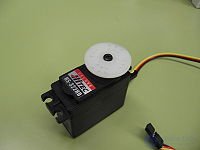
A servo motor is a servo drive with a motor, designed to move the output shaft to a required position (in accordance with a control signal) and to automatically and actively hold that position.
Servo motors are used to drive devices controlled by shaft rotation — such as opening and closing valves, switches, and so on.
Important characteristics of a servo motor are the motor's dynamics, smoothness of motion, and energy efficiency.
Servo motors are widely used in industry, for example in metallurgy, CNC machine tools, press-and-stamping equipment, the automotive industry, and railway traction rolling stock.
Servo drives mainly used 3-pole commutator motors, in which a heavy wound rotor rotates inside the magnets.
The first improvement that was applied — was an increase in the number of windings to 5. This increased the torque and the acceleration speed. The second improvement — was a change in the motor's design. A steel core with windings is very difficult to spin up quickly. Therefore, the design was changed — the windings are located outside the magnets, and rotation of the steel core is eliminated. As a result, the motor's weight decreased, the acceleration time decreased, and the cost increased.
And finally, the third step — the use of brushless motors. Brushless motors have higher efficiency, since there are no brushes or sliding contacts. They are more efficient, providing greater power, speed, acceleration, and torque.
A servo motor is a motor whose purpose is to operate over a wide speed range. This equipment improves smoothness of motion, reducing vibration as well as acoustic noise. This servo system usually includes a position sensor or a speed sensor. The servo motor receives a command from a frequency converter (inverter).
Modern servo motors are compact devices that provide optimal acceleration and braking, creating large accelerations and tractive force.
The advantages of modern servo drives and servo motors include:
Servo motors are not a separate class of electric motors, despite the fact that the term servo motor is often used to refer to an electric motor intended for use in a closed-loop control system.
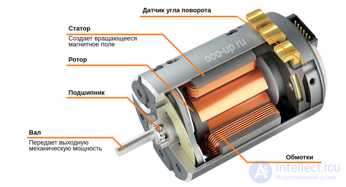
Electric motors intended for use in servomechanisms are usually subject to strict requirements. A key role in selecting a motor is played by its mechanical characteristic, as well as parameters determining dynamic characteristics, such as winding inductance and rotor moment of inertia. These parameters ultimately determine the overall parameters of the servomechanism. Large, powerful, slow-responding closed servo loops can use ordinary direct-current and alternating-current motors. But mostly, PMSMs and SRMs are used in servo motors, since they have better performance (power/volume, torque/inertia) compared with other motors. In servo systems, a motor design with a hollow rotor is widely used, which makes it possible to improve the dynamic characteristics of the system.

Comments