
Lecture
In the graphical method of calculating electrical circuits, the volt-ampere characteristics of nonlinear elements must be given (for example, in tabular form).
An electrical circuit is called nonlinear if it contains at least one nonlinear element.
The state of a nonlinear DC circuit in steady state can be described by a system of nonlinear algebraic equations written for the circuit diagram using Kirchhoff's laws. In mathematics there are no standard methods for solving systems of nonlinear algebraic equations, and, as a consequence, in practice there are no general methods for calculating nonlinear DC circuits, such as the mesh-current method and the node-voltage method used for linear circuits.
Electrical circuits may include passive elements whose electrical resistance depends substantially on current or voltage, as a result of which the current is not directly proportional to the voltage. Such elements, and the electrical circuits that contain them, are called nonlinear elements.
Nonlinear elements give electrical circuits properties unattainable in linear circuits (voltage or current stabilization, DC amplification, etc.). They can be uncontrolled or controlled. The former — two-terminal devices — are designed to operate without an external control factor acting on them (semiconductor thermistors and diodes), while the latter — multi-terminal devices — are used when a control factor acts on them (transistors and thyristors).
Let us consider the simplest nonlinear electrical circuit (Fig. 1.73), for which the VAC of the nonlinear element and E= 15 V are given.
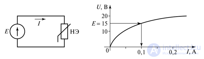
Fig. 1.73. Simplest nonlinear circuit and VAC of the nonlinear element
For such a circuit, calculating the current is trivially simple. We lay off the voltage across the nonlinear element (NE) E = UH3 = 15 V on the VAC and determine the current from the graph / = 0.1 A.
If two series-connected nonlinear elements are included in the circuit, a single current flows through them and the voltages add up (Kirchhoff's second law); consequently, if the VACs of the series-connected elements are given, one can, by summing the voltage values on the graph at a given current, construct a combined characteristic, i.e., simplify the circuit down to an elementary one. The graphs are added as follows (Fig. 1.74):
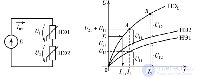
Fig. 1.74. Series connection of nonlinear elements
6. The current in the circuit is determined from the resulting VAC.
When nonlinear elements are connected in parallel, the voltage across them is the same, and the currents add up (Kirchhoff's first law). Consequently, the VACs of parallel-connected elements must be added at a given voltage (horizontally).
The graphical calculation method for a combined connection of nonlinear elements consists of successively transforming the circuit (adding series elements at a given current and parallel elements — at a given voltage) down to the simplest form. After that, the currents in the branches and the voltages across the elements are determined from the VAC.
a) series connection
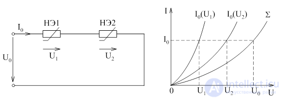
Since with a series connection of elements the total circuit voltage equals the sum of the voltages across the elements, the overall volt-ampere characteristic (VAC) can be obtained by summing the VACs of the elements along the voltage axis. Then, for a given U0, it is easy to determine the current I0 and the voltages U1 and U2.
b) parallel connection
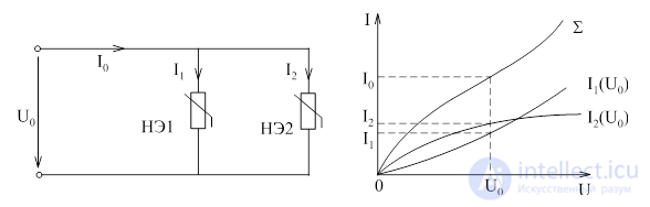
With a parallel connection, the overall VAC of the circuit is obtained by summing the VACs of the elements along the current axis.
c) mixed connection
With a mixed connection, the VAC of the circuit can be constructed step by step, using the rules for series and parallel connections.
Let us consider this method using the example of a series connection of nonlinear element NE1 and linear element R2 (Fig. 12).
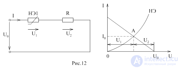
The characteristic of the nonlinear element I1=f(U1) is plotted in the usual way. The inverted characteristic of the linear element, which is a straight line, can be constructed from two points. If U2=0, then point "B" belongs to the characteristic I2=f(U2); if U1=0, then the characteristic I2=f(U2) crosses the ordinate axis at point "C", determined by the relation I2 = U0/R .
The intersection point of the two graphs gives the solution to the problem.
The graphoanalytical method is applicable for calculating circuits and loops containing a single nonlinear element, and is a variant of the equivalent generator method. The method consists in representing the electrical circuit, with respect to the nonlinear element, as an equivalent EMF source Eeq with internal resistance Rin (Fig. 1.75).
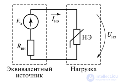
Fig. 1.75. Diagram of a loaded equivalent EMF source
The equation written using Kirchhoff's second law for this circuit is as follows:  , where Uoc— is the open-circuit voltage, i.e. at a load resistance equal to infinity. Since the circuit in open-circuit mode has a linear character, the voltage Uoc can be determined by writing equations from Kirchhoff's laws, and Rin can be calculated for the circuit in which all sources are replaced by their internal resistance. The equation
  represents the volt-ampere characteristic of the linear circuit. This VAC passes through the points:
• at /ne = 0 the voltage (Une = Uoc(open-circuit mode);
• at UNE = 0 the current  (short-circuit mode).
The linear VAC of the circuit (Fig. 1.76) is called the load line.
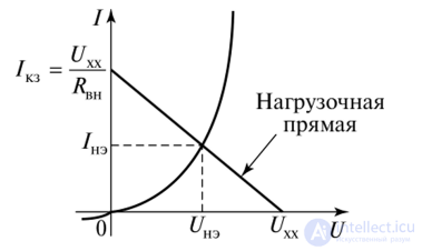
Fig. 1.76. VAC of the nonlinear element and the load line
The intersection of the load line with the VAC of the nonlinear element gives the sought solution — current /ne and voltage UNE.
The linear approximation method belongs to approximate calculation methods and consists in representing the nonlinear VAC of an element as a broken line, i.e. over different ranges of voltage or current variation the nonlinear element is replaced by one or several linear elements. For example, the VAC of a rectifier diode can be represented as a piecewise-linear characteristic (Fig. 1.77).
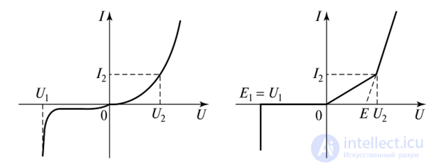
Fig. 1.77. Linear approximation of a diode's VAC
The linear VAC at U = U1, corresponds to an ideal voltage source (E1)), in the range U1 < U < 0 — to an open circuit, in the range 0 < U < U2 — to a linear resistor, for U2 < U < °° — connected in series with a resistor and a voltage source. Calculating linear circuits separately for each voltage range makes it possible to assess the operation of the circuit as a whole. The accuracy of the calculation depends on the level of approximation, i.e. on the number of linear segments on the VAC. Increasing the calculation accuracy leads to a substantial increase in complexity. This method is used for a preliminary assessment of the operation of an electronic circuit, selection of input signal ranges, and component ratings.
If the nonlinear circuit contains only one nonlinear element NE with a given VAC, then the calculation of currents and voltages in such a circuit can be performed by the combined method in three stages.
Stage 1. The branch containing the nonlinear element NE is isolated, and the remaining part of the circuit is replaced by an equivalent generator (Fig. 209a). The parameters of the equivalent generator Eeq and R0 can be determined analytically by any of the methods for calculating linear circuits, since the remaining part of the circuit no longer contains nonlinear elements.
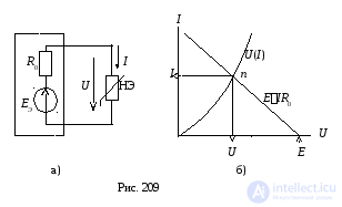
At Stage 2, a graphical calculation of the equivalent circuit of Fig. 209a is performed, typically by the method of counter-plotting the diagrams. From the equation of Kirchhoff's second law for the circuit of Fig. 209a, it follows that  . To graphically solve this equation, a straight line is drawn according to the equationU = E IR0 in the same coordinate system where the VAC diagram U(I) of the nonlinear element is given. The position of the operating point n corresponds to the intersection point of the line with the given VAC diagram U(I). The advantage of this method is that it does not require graphical addition of the VAC diagrams of the individual elements. As a result of the graphical calculation, the voltage U and current I of the nonlinear element are determined.
At the final Stage 3, the nonlinear element NE in the original circuit is replaced, in accordance with the compensation theorem, by an ideal EMF source with E=U, directed opposite to the current I. This substitution makes it possible to turn the original circuit from nonlinear into linear. The circuit after such a substitution is calculated using one of the methods for calculating complex linear circuits, as a result of which all currents and voltages in the original circuit are determined.
The combined calculation method can be applied to a complex circuit with two or more nonlinear elements.
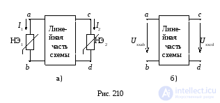
Let a complex circuit contain two nonlinear elements NE1 and NE2 (Fig. 210a).
At Stage 1, both nonlinear elements are isolated simultaneously from the complex circuit (Fig. 210a). The open-circuit mode is carried out simultaneously for both branches (Fig. 310b), and the open-circuit voltages Uxxab = a b and Uxxcd = c d are determined analytically. In accordance with the equivalent generator theorem, the linear part of the circuit is replaced by an equivalent generator (an active two-port network) as shown in Fig. 211.
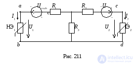
The internal resistances of the generator (R1, R2, R3) are calculated by reducing the linear part of the circuit (without sources) to an equivalent star (wye) circuit.
At Stage 2, a graphical calculation of the equivalent circuit (Fig. 14) is performed using one of the graphical methods discussed earlier; as a result of the graphical calculation, the currents and voltages of the nonlinear elements are determined (U1, U2, I1, I2). At the final stage, the currents and voltages on the elements of the linear part of the circuit are determined.
If the original circuit contains three or more nonlinear elements, the equivalent generator method can also be applied to it, in which case the linear part of the circuit is replaced by an active six-terminal or higher-order network, which, given a large number of nonlinear elements, does not yield a positive effect.
Nonlinear electrical circuits are calculated using graphical and analytical methods, based on Kirchhoff's laws and the current-voltage characteristics of individual elements in AC circuits for converting alternating current into direct current.
In the graphical calculation of an electrical circuit with two series-connected nonlinear resistors R1 and R2 with current-voltage characteristics I(U1) and I(U2), the current-voltage characteristic of the whole circuit I(U), where U = U1+U2, is constructed by summing the abscissas of the points of the current-voltage characteristics of the nonlinear resistors having equal ordinates (Fig. 3, a, b).
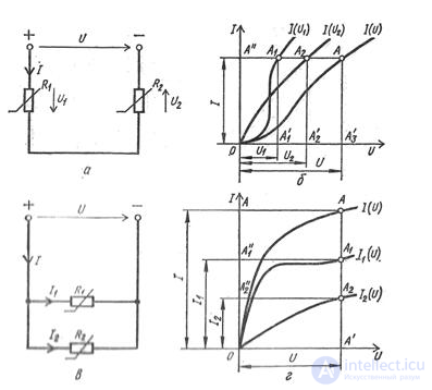
Fig. 3. Circuits and characteristics of nonlinear electrical circuits: a - series connection circuit of nonlinear resistors, b - current-voltage characteristics of the individual elements and the series circuit, c - parallel connection circuit of nonlinear resistors, d - current-voltage characteristics of the individual elements and the parallel circuit.
The presence of this curve makes it possible to find the current I from the voltage U, as well as the voltages U1 and U2 at the terminals of the resistors.
The calculation of an electrical circuit with two parallel-connected resistors R1 and R2 with current-voltage characteristics I1(U) and I2(U) is performed similarly, for which the current-voltage characteristic of the whole circuit I(U), where I = I1+I2, is constructed, from which, using the given voltage U, the currents I, I1, I2 are found (Fig. 3, c, d).
The analytical method for calculating nonlinear electrical circuits is based on representing the current-voltage characteristics of nonlinear elements by equations of the corresponding mathematical functions, which makes it possible to formulate the necessary state equations of electrical circuits. Since solving such nonlinear equations often involves considerable difficulty, the analytical method for calculating nonlinear circuits is convenient when the working sections of the current-voltage characteristics of nonlinear elements can be linearized. This makes it possible to describe the electrical state of the circuit with linear equations that present no difficulty in their solution.

Comments