
Lecture
An electric motor is an electrical machine (electromechanical converter) in which electrical energy is converted into mechanical energy through the interaction of the electromagnetic fields of the stator and rotor.
The operation of the vast majority of electrical machines is based on the principle of electromagnetic induction. An electrical machine consists of a stationary part — the stator (for AC induction and synchronous machines), a moving part — the rotor (for AC induction and synchronous machines) or the armature (for DC machines). Permanent magnets are very often used as the field source in low-power DC motors.
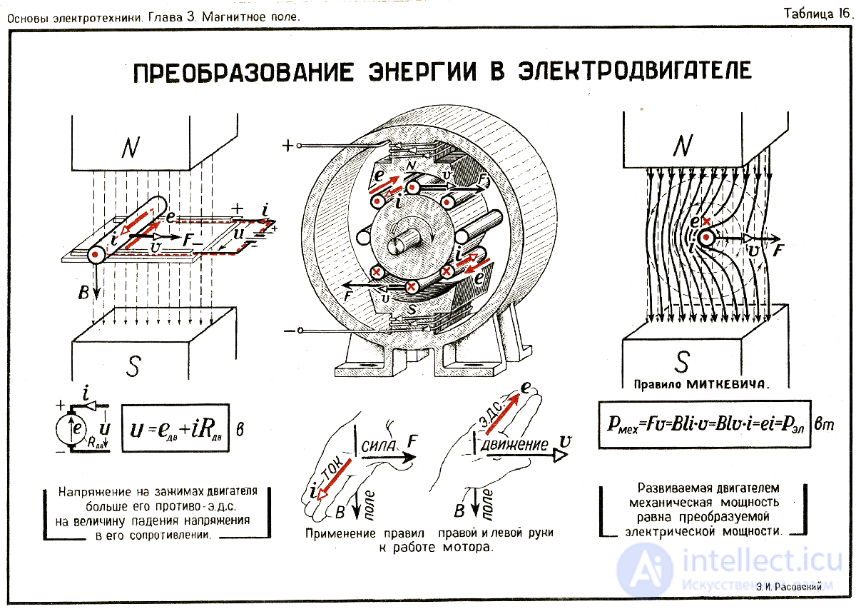
Fig. energy conversion in an electric motor
The rotor of an induction motor can be:
The armature is the rotating element of commutator DC machines or universal commutator machines (motor or generator).
A universal motor is the same DC motor (DCM) with series, shunt or compound excitation, distinguished by the design of the magnetic systems of the stator and armature. Since, when operating on alternating current, parasitic eddy currents are induced in massive magnetically soft parts, heating the motor, the pole systems of both the stator and the armature are built up from thin laminations insulated from one another. Nowadays the stator pole system is often made by winding a lacquered steel strip edgewise, followed by pressing and punching out the pole shoes. The magnetic systems of DC motors are made from a section of a solid steel tube, to the inside of which massive pole shoes are attached.
A DC motor (DCM) — is an electric motor designed to convert mechanical energy into direct-current electrical energy (generator) or to perform the reverse conversion (motor). A DC machine is reversible.
A DC machine is formed from an inverted synchronous machine design if its armature is fitted with a commutator, which in generator mode acts as a rectifier, and in motor mode — as a frequency converter. Owing to the presence of the commutator, alternating current flows through the armature winding, while in the external circuit connected to the armature it is direct current.
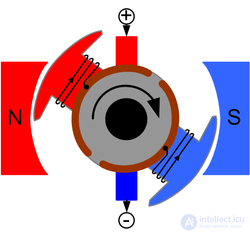
The following types of DC machines are distinguished:
A DC machine can operate in two modes: motor mode and generator mode, depending on which type of energy is supplied to it — if electrical energy is supplied, the electric machine will operate as a motor, and if mechanical energy is supplied, it will operate as a generator. However, electric machines are, as a rule, designed by the manufacturer for one specific mode of operation — either generator mode or motor mode.
DC motors are found on almost every automobile — the starter, the windshield-wiper drive, the cabin heater fan, and others.
The stator, on which the field winding is located, acts as the field system. A direct current is applied to it, as a result of which a constant magnetic field is created around it. The armature winding consists of conductors energized through the commutator. As a result, Ampere force pairs act on them, producing a rotating torque. The direction of the forces is determined by the "left-hand rule." However, this torque is able to rotate the rotor only 180 degrees, after which it would stop. To prevent this, a brush-commutator assembly is used, which acts as a pole switcher and as a rotor position sensor (RPS).
In a DC generator (DCG), the stator likewise serves as the field system, creating a constant magnetic field between the corresponding poles. As the rotor turns, an EMF is induced, by the law of electromagnetic induction, in the conductors of the armature winding as they move through the magnetic field, its direction being determined by the right-hand rule. The alternating EMF of the armature winding is rectified by means of the commutator, through stationary brushes, by which the winding is connected to the external network.
Automotive DC generators were fitted on old cars (GAZ-51, GAZ-69, and others); from the 1970s they were displaced by three-phase AC alternators with a three-phase rectifier on six diodes based on Academician Larionov's circuit.
Any electric machine can operate either as a generator or as a motor, so their designs do not differ.
A DC machine consists of two parts: a stationary one – the stator, and a moving one – the rotor.
The stator is a hollow steel cylinder – the frame – on the inner surface of which are located the poles of the magnetic system that produce the magnetic flux of the electric machine (Fig. 1.3).
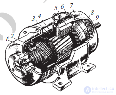
Fig. 1.3. Design of a DC electric machine:
1 – commutator; 2 – brushes; 3 – armature core; 4 – main pole core; 5 – field winding coil; 6 – frame; 7 – bearing shield; 8 – fan; 9 – armature winding
Depending on the method of producing the magnetic flux, DC machines are divided into those with permanent-magnet excitation and those with electromagnetic excitation. With permanent-magnet excitation, the poles of the DC machine's magnetic system are formed by permanent magnets. This type of excitation is used in low-power machines.
In a DC machine with electromagnetic excitation, the pole of the magnetic system is created by an electromagnet, which is a ferromagnetic core with a winding called the «field winding», through which
direct current flows. The poles that produce the main magnetic flux are called the main poles (Fig. 1.4).
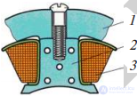
Fig. 1.4. Main pole: 1 – frame; 2 – core; 3 – field coil
Additional poles can be installed between the main poles, by means of which the distortion
of the main magnetic field caused by the load on the DC machine is corrected. The effect of the correcting magnetic
field of the additional poles makes it possible to reduce sparking between the brushes and the commutator.
The part of a DC machine that produces the magnetic flux is called the inductor (field system).
The rotor (Fig. 1.5) is built up from individual laminations of electrical steel, insulated from one another in order to
reduce eddy-current losses, and mounted on the shaft.
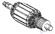
Fig. 1.5. Rotor of a DC machine
On the outer surface there are slots, into which the rotor winding is laid. The winding consists of individual coils that are connected to one another.
Coil – an elementary part of the rotor winding (Fig. 1.6). It may consist of one or several turns. In the
rotor's slots, the coil is laid in such a way that one part of it lies under the north pole of the magnetic system, and the other – under the south pole. The part of the coil located in the slot under a pole is called the active side of the coil. Each coil contains two active sides, which are joined by the end connections.
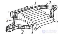
Fig. 1.6. Winding coil: 1 – active sides of the turn; 2 – end connections of the turn; 3 – core slots
The points where the coils are connected to one another are connected to the commutator, which is fixed on the shaft. The commutator (Fig. 1.7)
is a cylindrical assembly made up of cadmium-plated copper segments (to increase wear resistance). The segments are mounted on an insulating base and are insulated from one another. The number of commutator segments
depends on the number of points where the coils are connected to one another.
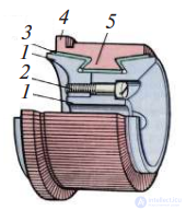
Fig. 1.7. Commutator: 1 – steel washers of the hub; 2 – tightening bolt; 3 – micanite insulation; 4 – riser (commutator lug); 5 – commutator segments
Brushes, attached to the frame and insulated from it, are pressed against the outer surface of the commutator (Fig. 1.8).
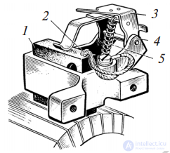
Fig. 1.8. Example of a brush assembly design
To connect the armature and field windings, us… By means of the commutator and brushes, the rotating rotor winding is electrically connected to the external circuit. An EMF appears in the DC machine's rotor winding, both in motoring and generating modes, which is why the rotating part of a DC machine is called the armature.
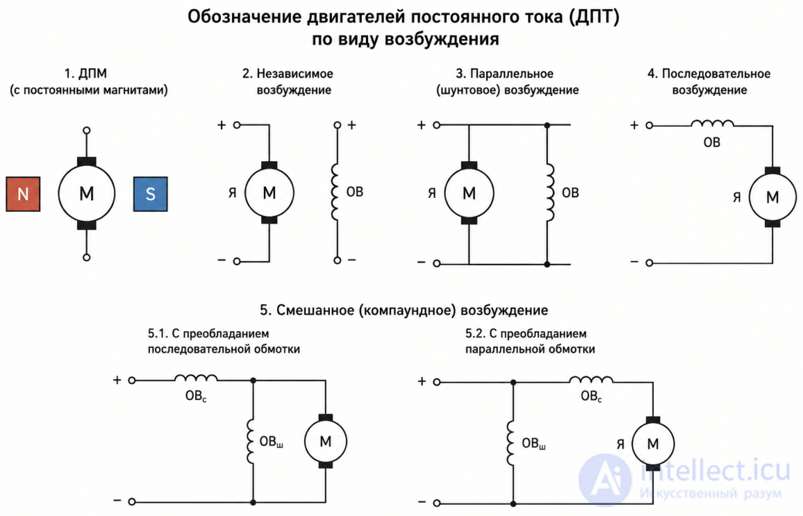
Thus, two electrical circuits can be distinguished in the design of a DC machine: the field circuit and the armature circuit. Depending on how they are connected to one another, DC machines are divided into machines with separate, shunt, series, and
compound excitation (Fig. 1.9).
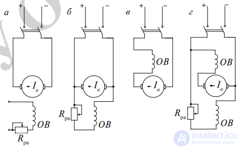
Fig. 1.9. Diagrams of DC machines with separate (a), shunt (b), series (c), and compound (d) excitation
1. Determine the polarity of the electromagnets in Fig. 3.1, a, and label them with letters. Determine the direction of the EMF in a conductor moving in a magnetic field with velocity v. Draw the magnetic field lines between the poles of the electromagnets shown in Fig. 3.1, b, and use arrows to indicate their direction, given the direction of motion of the conductor and the direction of the EMF induced in the moving conductor. Determine the polarity of the voltage at the terminals of the electromagnet winding.
Solution. Let us determine the direction of the magnetic field lines between the poles and the polarity of the electromagnets (see the right-hand rule).
In Fig. 3.1, a, the upper pole is north, the lower pole is south.
The direction of the EMF in the conductor is «toward us». In Fig. 3.1, b, the upper pole is north. The lower pole is south. The upper terminal of the electromagnet winding is positive, the lower one is negative.
2. State the law of electromagnetic induction using the example of the magnet shown in Fig. 3.2. Determine and indicate the direction of the EMF induced in a conductor moving in a uniform magnetic field perpendicular to the field lines with velocity v (Fig. 3.2).
Solution. The law of electromagnetic induction.
Its essence is as follows: if a conductor moves in a magnetic field perpendicular to the lines of force with a velocity v, then an EMF is induced in the conductor, determined by the formula 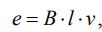 ,V, where v – is the linear velocity of the conductor in m/s. Let us determine the direction of the EMF induced in the conductor (see the right-hand rule). The direction of the conductor's EMF is «away from us».
Problem 3.2 [1, p. 27-29; 2, p. 7-10; 4, p. 4-7].
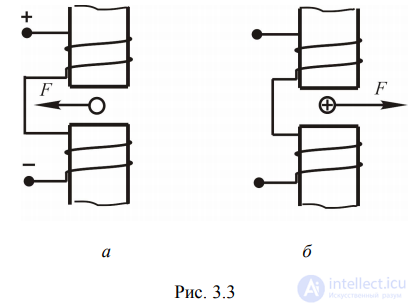
1. Determine the polarity of the poles in Fig. 3.3, a and 3.3, b and label them with letters.
Solution. The polarity of the applied voltage and the application of the right-hand screw rule indicate that in Fig. 3.3, a
the upper pole is north, and the lower pole is south. Using the left-hand rule, we determine the direction of the current in the conductor. The current
in the conductor flows «away from us».
2. Draw the magnetic field lines and indicate their direction with arrows for the electromagnet shown in Fig. 3.3, b. Determine the polarity of the applied voltage.
Solution. Let us determine the direction of the magnetic lines of force between the poles and the polarity of the electromagnets (see the left-hand
rule). The upper pole is south, the lower pole is north. The right-hand rule indicates that the lower terminal of the electromagnet's winding is connected to the positive terminal of the source, while the upper terminal is connected to the negative terminal.
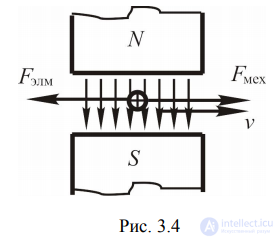
3. A conductor moves in a uniform magnetic field perpendicular to the lines of force (Fig. 3.4) with a velocity v. Determine the forces acting on a conductor moving in a magnetic field.
Solution. In accordance with the law of electromagnetic induction, an electromotive force is induced in a conductor moving in a magnetic field, the direction of which is determined by the right-hand rule.
If the conductor's external circuit is closed, a current will flow through the conductor, coinciding in direction with the EMF.
In order for the conductor to move in the magnetic field with a velocity v, an external mechanical force must be applied to it
F_mech. At the same time, according to the law of electromagnetic forces, an electromagnetic force F_em, whose direction is opposite to the direction of the external mechanical force, acts on the current-carrying conductor located in the magnetic field.
Thus, if a conductor carrying an electric current i, of length
l, moves in a magnetic field with induction B, then a force interaction arises between the current-carrying conductor and the magnetic field. The value of the electromagnetic force acting on the conductor is determined by the formula 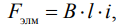 ,N.
,N.
Let us determine the direction of the electromagnetic force (see the left-hand rule). The direction of the external mechanical force acting on the conductor
is opposite to the direction of the electromagnetic force.
Problem 3.3. Design of a DC machine [1, p. 33-38; 2, p. 337-341; 3, p. 35-41; 4, p. 458-466; 5, p. 30-32; 6, p. 8, 9; 7, part 2, p. 199-203].
Draw a sketch of a DC machine (Fig. 3.5).
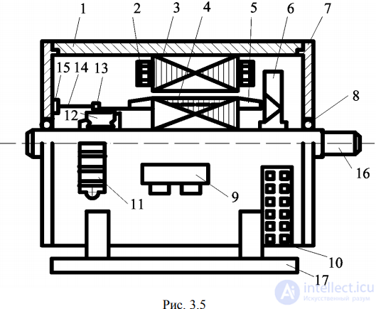
Describe the main structural elements:
1 – frame; 2 – field winding; 3 – main pole core; 4 – armature core; 5 – armature winding; 6 – fan; 7 – bearing shield; 8 – bearing; 9 – terminal box; 10 – hatch; 11 – hatch window; 12 – commutator; 13 – brush holder with brush; 14 – brush finger; 15 – brush
rocker (yoke); 16 – shaft; 17 – feet.
When constructing the sketch, one must start by drawing the active part of the DC machine (elements 4, 5, 2, 3, 1, 12), and then add the structural elements.
Frame 1 is a hollow steel cylinder. At its end it is provided with annular grooves for the entry of annular projections
bearing shields 7. The point where the shield joins the frame is called the fit. The frame is fitted with hatches that serve for the inflow and outflow of cooling air, as well as for access to the commutator-brush assembly.
The hatch (window) on the commutator side is closed by cover 11, fitted with louvers for the passage of cooling air and hoods to protect against drops and water splashes falling at an angle. The hatch on the fan side 10 (mainly at the bottom) is closed with a perforated protective band.
Field winding 2 is placed on the main pole core 3 and is made of copper wire. The frame is fitted with feet 17 for mounting to the foundation and with a lifting ring (eyebolt) or two diagonal lifting lugs. Mounted on shaft 16 is
armature core 4. It is made of electrical steel laminations, stacked perpendicular to the shaft axis, which are fitted with slots
along their outer periphery. Armature winding 5 is placed in the slots. The winding is made of copper wire, often of round cross-section
(a random-wound winding), but the wire can also be of rectangular cross-section (form-wound coils). The winding itself consists of individual elements called coils. The coils are connected to one another in series, forming a closed system of conductors – such a winding is called a closed-type (lap or wave) winding. The end of the preceding coil and the start of the following one are soldered to a commutator bar of commutator 12.
The commutator is likewise assembled from copper bars, most carefully insulated from one another and from the machine shaft. They can be of the built-up (assembled) type or molded in plastic. By assembly type, commutators are divided into cylindrical and face types. Brushes, housed in brush holders 13, are pressed against the working surface of the commutator by springs. The brush holder is attached to pin 14, which can be made of insulating material or of metal, in which case it is insulated from the brush holder. The pin is attached to brush rocker 15, which in turn is attached to the bearing shield and is fitted with slots for moving the rocker around the circumference in order to set the brushes to the required position. Terminal box 9 is attached to the frame.
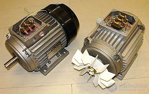
AC motor — an electric motor powered by alternating current. By principle of operation, these motors are divided into synchronous and asynchronous (induction) motors. The fundamental difference is that in synchronous machines the first harmonic of the stator's magnetomotive force moves at the speed of rotation of the rotor (owing to which the rotor itself rotates at the speed of rotation of the stator's magnetic field), whereas in asynchronous machines there is always a difference between the rotor's speed of rotation and the speed of rotation of the stator's magnetic field (the field rotates faster than the rotor).
Synchronous motor — an AC electric motor whose rotor rotates synchronously with the magnetic field of the supply voltage.
Synchronous motors are subdivided into :
There exist synchronous motors with discrete angular displacement of the rotor — stepper motors . In these, the specified rotor position is fixed by applying power to the corresponding windings. Transition to another position is carried out by removing the supply voltage from some windings and transferring it to others. Another type of synchronous motor is the switched reluctance motor, whose winding power is generated using semiconductor elements.
An induction motor — is an AC electric motor in which the rotor speed differs from the frequency of the rotating magnetic field created by the supply voltage. These motors are the most widespread today.
By the number of phases, AC motors are classified into:
By appearance, full-size household motors and small motors, which some manufacturers call "cup", can be distinguished.
Depending on the way the air flow passes through, household motors are divided into flow-through (in-line) and bypass types.
In in-line (flow-through) household motors, air is drawn in by the turbine and then passes on through the motor windings, thereby cooling it. Given this feature, such motors can only be used in vacuum cleaners for dry cleaning. Special attention is paid to the vacuum cleaner's filters, since dust getting onto the motor's windings and brushes leads to overheating and rapid failure. As a rule, small in-line motors are used in household vacuum cleaners.
In bypass household motors, air is drawn in by the turbine and then expelled through special openings on the side of the motor, without coming into contact with the motor windings, which is what gave this type of motor its name: the air, as it were, goes around ("bypass"). To cool the windings of such motors, an additional fan impeller is installed at the top of the motor.
By the method of air discharge bypass household motors are divided into two types: peripheral and tangential.
The peripheral system implies the presence of several openings around the entire circumference of the motor, into which the drawn-in air is blown out.
The tangential system works as follows: air is drawn in by the turbine, then, rotating in a circle, is expelled through a single outlet located on the side.
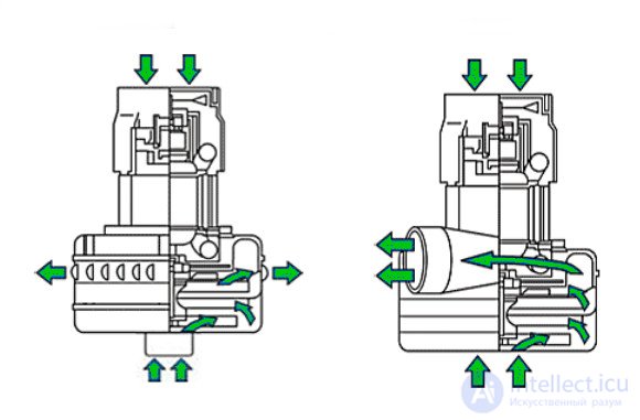
Since the intake air in such motors does not come into contact with the electrical part, they are used in various wet-cleaning vacuum cleaners, floor scrubbers, water vacuum cleaners, and dry-cleaning equipment. Tangential-type bypass motors are often used in central vacuum systems.
Staging (the number of stages) of motors.
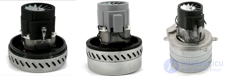
Vacuum motors come in single-stage, two-stage and three-stage versions (also may be called "two-step" or "three-step"). The staging of motors is used to increase the level of vacuum. Single-stage motors pass the maximum air flow through themselves, but have a low degree of vacuum. Adding stages increases the degree of vacuum but reduces the air flow due to increased resistance as air passes through the turbine impellers.
The staging of a motor can be determined visually by the height of the block where the impellers are located:
A universal commutator (brushed) motor is a commutator motor that can operate on both DC and AC. It is manufactured only with a series field winding, for power ratings up to 200 W. The stator is laminated (built up from individual sheets) from special electrical steel. The field winding is partially engaged on AC and fully engaged on DC. For AC, the rated voltages are 127 and 220 V; for DC, 110 and 220 V. It is used in household appliances and power tools. AC motors powered from a 50 Hz industrial supply cannot achieve rotational speeds above 3000 rpm. Therefore, to obtain higher speeds, a commutator motor is used, which is also lighter and smaller than an AC motor of the same power, or special gear mechanisms are used to change the kinematic parameters of the mechanism to the values required (speed multipliers). When frequency converters are used, or when a higher-frequency supply is available (100, 200, 400 Hz), AC motors turn out to be lighter and smaller than commutator motors (the commutator assembly sometimes takes up half the space). The service life of AC induction motors is much higher than that of commutator motors, and is determined by the condition of the bearings and winding insulation.
A synchronous motor with a rotor-position sensor and an inverter is the electronic analog of a DC commutator motor. Strictly speaking, a universal commutator motor is a DC commutator motor with series-connected field (stator) windings, optimized for operation on the AC of a household electrical network. This type of motor rotates in the same direction regardless of the polarity of the applied voltage, because, due to the series connection of the stator and rotor windings, the reversal of the poles of their magnetic fields occurs simultaneously, and the resulting torque remains directed in the same direction. To enable operation on AC, the stator is made of a magnetically soft material with low hysteresis (resistance to remagnetization). To reduce eddy-current losses, the stator is made up of laminated, insulated sheets. A feature (in most cases an advantage) of operating such a motor specifically on AC (rather than on DC of the same voltage) is that, in the low-speed mode (starting and overload), the inductive reactance of the stator windings limits the current drawn and, correspondingly, the maximum torque of the motor (approximately) to 3—5 times the rated value (versus 5—10 times when the same motor is supplied with DC). To bring the mechanical characteristics closer together, general-purpose motors may use sectioning of the stator windings — separate taps (and a smaller number of stator winding turns) for connecting to AC.
Its principle of operation is that the moving part of the motor consists of permanent magnets mounted on a rod. AC current is passed through the stationary windings, and the permanent magnets, under the action of the magnetic field created by the windings, move the rod back and forth.

Comments