
Lecture
Two-phase motor is an AC electric motor with two windings spatially offset by 90°. When a two-phase current, shifted in phase by 90°, is applied to the motor, a rotating magnetic field is produced. The motor's squirrel-cage rotor is usually made in the form of a «squirrel cage». Usually the number of bars of the squirrel-cage rotor is not related to the number of stator pole pairs, that is, with two stator pole pairs the number of rotor bars can be, for example, 14. There are certain considerations according to which the number of rotor bars should be related to the number of rotor poles.
If one of the three supply wires of a rotating three-phase induction motor is broken, then under a light load it will continue to run on a single phase. A rotating field remains in the motor. However, when started at rest on a single phase, such a motor will not run even without a load. If the third winding phase is connected through a capacitor to one of the two supply wires, then a three-phase motor connected to a single-phase mains will start running, and its operating characteristics will be similar to those of an ordinary three-phase induction motor.
Rotating magnetic fields can also be created by two-phase windings if these windings are spatially offset by 90° relative to each other. If these windings are powered by two currents offset by 90° in phase, then, as in a three-phase motor, a rotating magnetic field results.
In a two-phase motor, torque is created due to the currents induced by the rotating magnetic field in the bars of the motor's rotor. The rotor accelerates until it — just as in a three-phase induction motor — reaches a certain final rotational speed, which is lower than the rotational speed of the field.
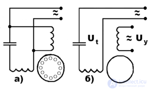
If both stator windings are powered from one and the same single-phase mains, then the phase shift in one of the windings, needed to obtain a rotating field, can be achieved by connecting a capacitor of sufficient capacitance in series . The figure shows the circuit of a two-phase induction motor with a capacitor when powered from an AC mains.
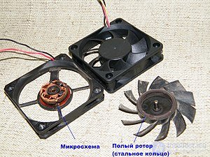
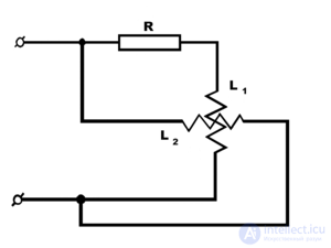
A phase shift in one of the windings can also be obtained by connecting a resistor in series, but in this case the active power losses increase. A phase shift is also obtained if, instead of an external resistor, a short-circuited turn is placed on the pole (or poles) of one of the windings. In this case, the active power losses in the corresponding winding increase, but the external resistor is eliminated. Such motors usually have low power and are used, for example, in household fans .
Nowadays, the field of application of the two-phase induction motor in the form of a hollow-rotor motor has expanded. In such a motor, instead of an ordinary squirrel-cage rotor, an aluminum cylinder is used, which can rotate in the air gap between the outer and inner stators.
The rotating field induces eddy currents in the aluminum cylinder, which, interacting with the magnetic field in the air gap, produce torque. The cylinder reaches a final asynchronous speed that corresponds to the load on the shaft.
The small moment of inertia of the motor's rotor results in favorable operating characteristics. Hollow-rotor motors are designed primarily for low power and are used for automatic control in compensation and bridge circuits. One of the windings, together with a capacitor, is connected to the supply voltage network, while a control voltage is applied to the second winding.

Comments