3D Model
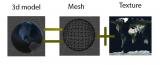
I think we all know perfectly well here what a 3D model is and what it consists of.
But just in case, I want to clarify two points that are important for us:
1. Vertex. Each vertex has its own coordinates, as well as a normal.
Vertices are joined into polygons by means of edges, and polygons, in
turn, form a polygon mesh.
2. Texture. A texture is a simple image that is placed on
the model in accordance with uv coordinates.
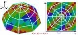
UV coordinates – the correspondence between the coordinates on the surface of a three-dimensional object (X, Y, Z) and the coordinates on the texture (U, V). The values of U and V usually range from 0 to 1. That is, each vertex of the model has its own corresponding coordinates on the texture. Why are there only 2 of them? It's simple. U corresponds to X on the texture, V corresponds to Y.
Shaders
A shader - is a program that runs on the graphics processing unit (GPU) of the video card. The shader's input consists of data containing information about vertex coordinates, polygons, normals, lighting, vertex color, UV (texture coordinates), etc. The shader's task is to take this data, process it, and output the final result.
Schematically, the operation of a shader can be described as follows:
1. Receiving input data
2. Processing the data
3. Outputting the final result ( an image )
4. Waiting for the next input data
It is also very important that a shader is executed separately for each individual vertex/pixel! In doing so, it only has information about the vertex/pixel it is currently processing. That is, while writing a shader we do not know what color the neighboring vertex/pixel is.
Pixel and Vertex Shaders
Vertex shader - a shader that processes data about a vertex and then passes it on to the pixel shader. We can decide for ourselves what data the shader will pass on, but we must always pass on (return) the coordinates of the current vertex (x,y,z). The vertex shader runs before the pixel shader, and data is then passed from it to the pixel shader.
Since there are significantly more pixels than vertices, it is obvious that the pixel shader is executed a greater number of times than the vertex shader. It is also worth understanding that after the vertex shader passes on the vertex data, this data is interpolated (smoothed) for each specific pixel. That is, if a pixel lies exactly between vertices A (black) and B (white), the color of that pixel will be calculated as the average of these two vertices (gray), and likewise for every parameter.
Pixel shader - a shader that receives interpolated data from the vertex shader and, based on it, computes the color for each individual pixel. Again, we can decide what data needs to be passed to the pixel shader, but we must always return a color.
So, now we know what a vertex and pixel shader are.
Let's make our shader operation algorithm a little more complex:
1. Receiving input data
2. Processing it in the vertex shader
3. Interpolating the data
4. Passing the data to the pixel shader
5. Processing the data in the pixel shader
6. Outputting the final result (an image)
I'll say in advance that there are 2 more types of shaders: geometry shaders (which work with whole primitives of the model) and surface shaders (a simplified type of shader in Unity 3D, mainly used for working with lighting).
Shader Programming Languages
GLSL - a high-level shading language for OpenGL
HLSL - a high-level programming language for DirectX
CG - a high-level programming language which, depending on the situation, is compiled into HLSL/GLSL. Used in Unity. That's what we need.
The CG Programming Language
The CG programming language is a high-level programming language developed by Nvidia for programming
pixel and vertex shaders.
Variable types in CG
Simple:
- float - a floating-point numeric variable (32 bits)
- half - a floating-point numeric variable (16 bits)
- fixed - a floating-point numeric variable (12 bits)
- int - integer numbers (32 bits)
- bool - boolean (1 bit)
Vectors:
- float2,float3,float4
- half2,half3,half4
- fixed2,fixed3,fixed4
2D, 3D and 4D vectors
Matrices
- float2x2,float3x3,float4x4
Texture:
- sampler2D - a 2D texture (3D textures also exist -; )
- samplerCUBE - a cube texture (used for
reflections)
To indicate that a variable is external, the keyword uniform is added in front of it.
Since the CG language was created specifically for writing shaders, it contains built-in geometric, physical, and algebraic functions for working with vectors, matrices, lighting, and so on.
Geometric:
- sin/ asin - sine/arcsine
- cos/ acos - cosine/arccosine
- tan/ atan / atan2 - tangent, arctangent, arctangent of two arguments
- dot - dot product of vectors
- cross - cross product of vectors
- length - length of a vector
- reflect - reflection vector
- normalize - returns a normalized vector
- degrees/ radians - converts radians to degrees / degrees to radians
- distance - distance between two points
Algebraic :
- mul - multiplies a matrix by a vector and vice versa
- pow - raises to a power
- lerp - linear interpolation
- exp - exponent to a power
- sqrt - square root
- log - logarithm
Physical:
- refract - refraction by an argument
Others:
the minimum/maximum value of each argument
- clip - discards pixels
- clamp - sets bounds for the returned number
- saturate - sets bounds for the number between 0 and 1
- tex2D - returns the color of a pixel from a texture at UV coordinates
- texCUBE - returns the color of a pixel from a cube texture by a vector
P.S. click on a function for a detailed description
P.S2. color is represented as a float4/half4/fixed4 variable
(Red, Green, Blue, Alpha), with each color component ranging from 0
to 1.
Model View Projection coordinates
Now let's figure out how our model gets rendered to the screen. Unfortunately, our screen operates in 2D mode. It can only output 2D images to us. That is, our task is to project the volumetric world onto a flat screen. Artists face the same task: depicting volume on flat paper. (If it's not clear what this is about, watch this video, and watch it again afterward.)
And this is done every single frame, so that there is a sense of moving through 3D space on the monitor.
Let's start from the beginning, with the model. More precisely, with a vertex of this model. What do we know about it? Only its coordinates (x,y,z). And these coordinates are local. That is, they are known to us in a coordinate system that is built relative to the model.
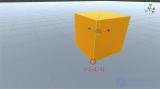
We need to place these coordinates on the screen so that we get a projection of the 3D world onto the 2D screen. Matrices will help us here. Briefly, in order to convert coordinates from one coordinate system to another, we need to multiply these coordinates by a special matrix (multiplying a vector by a matrix gives a vector). For example, in order to do some calculations in world coordinates (the coordinates of a vertex in "world space"), we need to convert the object coordinates of the vertex into world coordinates. To do this we multiply the object coordinates by the "world matrix" (4x4 WorldMatrix)*(x,y,z,) * WorldMatrix - the formula for calculating world coordinates
Now our coordinates have become world coordinates and we know exactly where this vertex is located in the game world. This means we can calculate lighting, shadows, highlights, and so on. All the other game objects are located in these same coordinates. But knowing only the world coordinates is not enough for us to project the model onto the screen. Moreover, we don't even know whether our model falls within the camera's field of view.
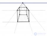
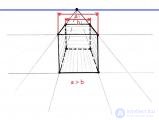
The next step for us will be converting the world coordinates into view coordinates (a coordinate system relative to the camera). This is done in the same way, by multiplying the world coordinates by the "view matrix" (ViewMatrix). As a result we have: (x,y,z,) * WorldMatrix * ViewMatrix Now we know the vertex coordinates relative to the camera. That's great, of course, but it's still not enough. This is not a projection. At this point none of our models are scaled depending on distance. In real life, when we look at a distant object, it appears small to us, and vice versa. That is, the farther we are from an object, the smaller it appears to us. In other words, we need to scale objects depending on the distance between the object and the camera!
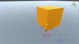
The front side of the cube, which is closer to us, is larger than the back side. Although, in reality, there is no front or back side here at all, since this is just a flat picture, but with the help of projection we get the impression that we are looking at a three-dimensional image. The same thing should happen for us. We need to create a projection. This is done, and I think you've already guessed it, by multiplying the camera coordinates by the projection matrix (ProjectionMatrix). And here is the final result that can be output: (x,y,z) * WorldMatrix * ViewMatrix * ProjectionMatrix All of the matrices (World View Projection) are set in the Unity engine. There is also a ready-made result of multiplying the three matrices together — UNITY_MATRIX_MVP. All of these operations, by the way, are performed in the vertex shader.
I'm sure that for many people this still isn't very clear.
For those who need detailed explanations of how this works
- In Russian, though the examples are in GLSL, but what matters to us is the underlying principle.
SEMANTICS
Another important question worth touching on is the semantics of the data entering/leaving the shader. Semantics in a shader determine
what type of data we want to receive as input or output: POSITION (position), TEXCOORD (uv coordinates), NORMAL (normal), etc. In a pixel shader, the semantics determine the type of interpolated data received from the vertex shader. Since, for example, there can be several sets of texture-coordinate data, a number is appended to the end of their semantics: TEXCOORD0, TEXCOORD1, TEXCOORD2
Main types of semantics:
- POSITION - the vertex position in object coordinates
- NORMAL - the normal vector
- TEXCOORD0 - texture coordinates
- COLOR - color
- TANGENT - tangent
- SV_POSITION - the same as POSITION
- SV_Target - the same as color
Color
In shader programming we constantly deal with color, so I will briefly touch on this topic. Color, as probably many people know, is encoded in computer graphics using three primary colors: red, green, and blue (r, g, b). To specify a color in CG, you need to use 4D (red, green, blue, alpha) vectors. Each component of this vector lies in the range from 0 to 1.
Operations with colors:
- Addition/subtraction – mixing colors. For example, red + green = yellow. It turns out that to mix colors, you need to add/subtract 2 vectors.
float4 red = float4(1,0,0,0)
float4 green = float4(0,1,0,0)
red+green = ( 1+0,0+1,0+0,0+0)  = (1,1,0,0).
- Multiplication/division of colors by each other – not a scalar multiplication.
We simply multiply the corresponding components of the vector by each other.
float4 white = float4(1,1,1,1)
float4 green = float4(0,1,0,0)
float4 ColorMult = white*green = (1*0,1*1,1*0,1*0) = (0,1,0,0).
From this we can conclude that multiplying any color by white gives exactly the same color, while multiplying any color by black gives black.
- Multiplying/dividing a color by a number is essentially just
increasing/decreasing the brightness of the color. We simply multiply each component
of the vector by the number.
float4 lessGreen = float4(0,0.5,0,0)
float4 green = lessGreen*2 = (0*2,0.5*2,0*2,0*2) = (0,1,0,0)
See also
- Principles of three-dimensional graphics
- Shaders
- CG
- Lighting models
- Semantics


Comments