
Lecture
Asynchronous electric motor — an alternating-current electric motor whose rotor speed is not equal to (in motoring mode, is less than) the rotation speed of the magnetic field produced by the current in the stator winding.
In a number of countries, commutator motors are also classed among asynchronous motors. The second name for asynchronous motors — induction motors, is due to the fact that the current in the rotor winding is induced by the rotating stator field. Today, asynchronous machines make up the larger part of electrical machines, being used mainly as electric motors, and are the principal converters of electrical energy into mechanical energy; in the vast majority of cases these are squirrel-cage induction motors (SCIM).
The operating principle of an asynchronous motor is that the current in the stator windings creates a rotating magnetic field. This field induces a current in the rotor, which begins to interact with the magnetic field in such a way that the rotor starts rotating in the same direction as the magnetic field. The rotor speed is always slightly lower than the rotation speed of the magnetic field, because if the speeds were equal the field would stop inducing current in the rotor, and the Ampère force acting on the rotor would cease. This is where the name — asynchronous motor — comes from (as opposed to a synchronous motor, whose rotation speed coincides with the frequency of the magnetic field). The relative difference between the rotor's rotation speed and the frequency of the alternating magnetic field is called slip. In steady-state operation, the slip is small: 1-8% depending on the power .
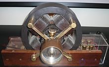
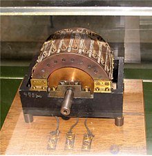
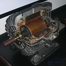
In 1888, Galileo Ferraris published his research in an article for the Royal Academy of Sciences in Turin (in the same year Tesla received a US patent ), in which he set out the theoretical foundations of the asynchronous motor . Ferraris's contribution lies in the fact that, having drawn the erroneous conclusion that the asynchronous motor had low efficiency and that the use of alternating-current systems was impractical, he drew the attention of many engineers to the problem of improving asynchronous machines. Galileo Ferraris's article, published in the journal «Atti di Torino», was reprinted by an English journal and in July 1888 came to the attention of a graduate of the Darmstadt Higher Technical School, a native of the Russian Empire, Mikhail Osipovich Dolivo-Dobrovolsky. Already in 1889, Dolivo-Dobrovolsky received a patent for a three-phase asynchronous motor with a squirrel-cage rotor (German patent No. 51083 of March 8, 1889, titled «Anker für Wechselstrommotoren»), and in 1890 — patents in England No. 20425 and Germany No. 75361 for a wound rotor with slip rings and starting devices. These inventions opened the era of mass industrial application of electrical machines. In 1903, a grain elevator was built in Novorossiysk with the world's first industrial three-phase alternating-current network, all of whose installations were manufactured under Dolivo-Dobrovolsky's direction. At this elevator, also for the first time in the world, three-phase transformers and wound-rotor asynchronous motors were used. At present, Dolivo-Dobrovolsky's asynchronous motor is the most widespread electric motor[
Advantages and disadvantages of a squirrel-cage induction motor compared to machines of other types:
Advantages:
All the above advantages are a consequence of the absence of mechanical commutators in the rotor circuit, and have led to the fact that most electric motors used in industry are squirrel-cage induction machines.
The disadvantages of an induction motor are due to its rigid characteristic:
The most effective approach to eliminating the above disadvantages is to power the motor from a static frequency converter.
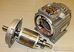
An induction machine has a stator and a rotor separated by an air gap. Its active parts are the windings and the magnetic core; all other parts are structural, providing the necessary strength, rigidity, cooling, the ability to rotate, etc.
The stator winding is a three-phase (in the general case, polyphase) winding, whose conductors are evenly distributed around the circumference of the stator and laid phase-by-phase in slots at an angular spacing of 120°. A combined winding is also known, which makes it possible to increase the motor's efficiency . The phases of the stator winding are connected according to standard «delta» or «wye» schemes and connected to a three-phase current mains. The stator magnetic core is remagnetized as the current in the stator winding changes, so it is assembled from sheets of electrical steel to ensure minimal magnetic losses. The main method of assembling the magnetic core into a stack is lamination.
By rotor construction, induction machines are divided into two main types: with a squirrel-cage rotor and with a wound rotor. Both types have the same stator construction and differ only in the design of the rotor winding. The rotor magnetic core is made in the same way as the stator magnetic core — from sheets of electrical steel.
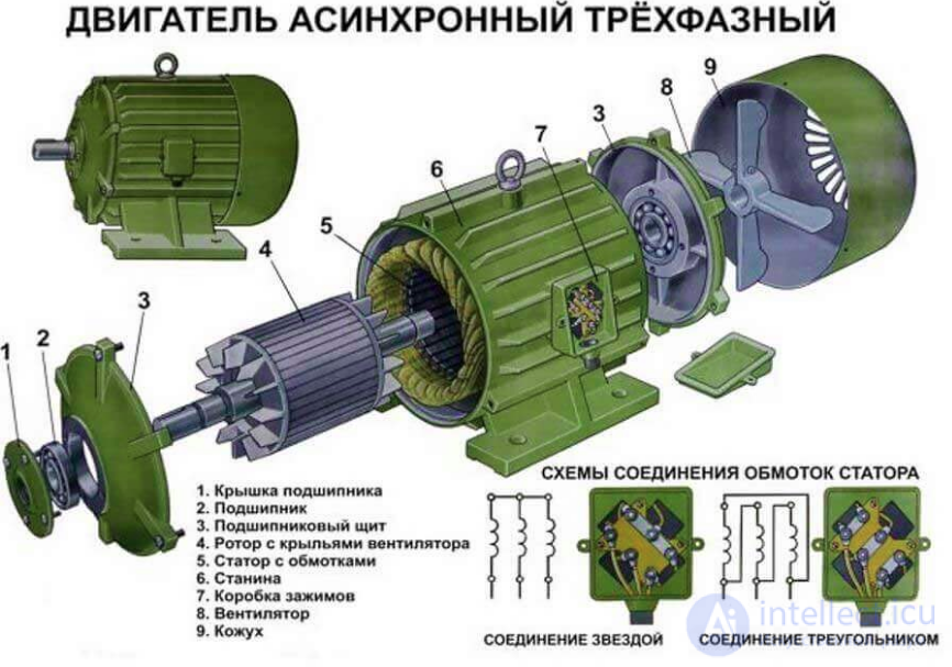
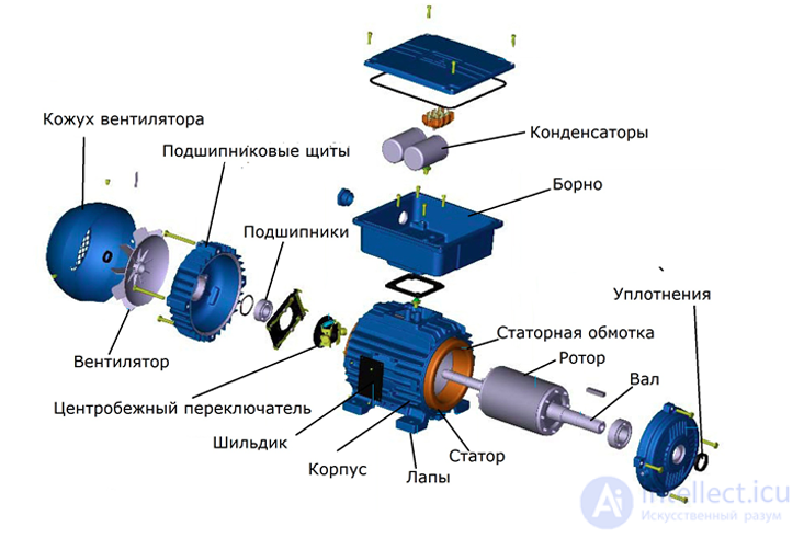
Fig. Construction of a single-phase induction motor
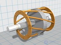
The squirrel-cage rotor winding, often called a «squirrel cage» because of the external resemblance of its construction, consists of aluminum (less often copper or brass) bars short-circuited at the ends by two rings. The bars of this winding are inserted into the slots of the rotor core. The rotor and stator cores have a toothed structure. In low- and medium-power machines, the winding is usually made by casting molten aluminum alloy into the slots of the rotor core. Together with the bars of the «squirrel cage», the short-circuiting rings and end fan blades, which ventilate the machine, are cast at the same time. In high-power machines, the «squirrel cage» is made of copper bars, the ends of which are joined to the short-circuiting rings by welding.
The rotor or stator slots are often skewed to reduce the higher-order EMF harmonics caused by pulsations of the magnetic flux due to the presence of teeth, whose magnetic reluctance is significantly lower than that of the winding, and also to reduce noise caused by magnetic factors.
To improve the starting characteristics of a squirrel-cage induction motor, namely to increase the starting torque and reduce the starting current, a so-called «double squirrel cage» made of bars with different resistivities was formerly used in the rotor; later, rotors with a specially shaped slot (deep-bar rotors) came into use. In this case, the part of the rotor slot farther from the axis of rotation has a smaller cross-section than the inner part. This makes it possible to use the current displacement (skin) effect, which increases the active resistance of the rotor winding at high slip values (in particular, during starting).
Squirrel-cage induction motors, when started direct-on-line (without regulation), have a small starting torque and a significant starting current, which is a substantial drawback. For this reason they are used in electric drives where large starting torques are not required. With the development of power semiconductor technology, frequency converters have become widespread; they allow the frequency of the current supplying the motor to be smoothly increased during starting, thereby achieving a large starting torque. Among their advantages are ease of manufacture and the absence of electrical contact with the moving part of the machine, which guarantees longevity and reduces maintenance costs. With a special rotor design, in which only a hollow aluminum cylinder rotates in the air gap, low motor inertia can be achieved.
A variant of the squirrel-cage induction motor that allows stepwise speed control is the multi-speed motor, in which speed control is achieved by changing the number of pole pairs in the stator, for which special types of windings have been developed.
It is precisely squirrel-cage induction motors that, owing to the above-mentioned advantages, are the main type of motor used in industrial electric drives; the use of other types of motors is minor and of a narrowly specialized nature.
There is a variant of induction machines with a solid rotor. Such a rotor is made entirely of ferromagnetic material, i.e., it is essentially a steel cylinder. The ferromagnetic rotor simultaneously serves as both the magnetic core and the conductor (instead of a winding). The rotating magnetic field induces eddy currents in the rotor, which, interacting with the stator's magnetic flux, produce torque.
Advantages:
Disadvantages:
Features:
There are various ways of improving solid rotors: soldering copper rings onto the end faces, coating the rotor with a layer of copper.
Machines with a hollow rotor can be considered separately. This can be a hollow cylinder made of ferromagnetic material or simply of a conducting material.
This type of electric motor allows smooth speed control over a wide range. The wound rotor has a multiphase (usually three-phase) winding, typically connected in a «star» (wye) configuration and brought out to slip rings. Using brushes sliding on these rings, an external control circuit is connected into the rotor winding circuit, which makes it possible to control the rotor speed. The elements of this circuit are:
Three-phase commutator induction motor with rotor-side power supply.
An inverted (rotor-fed) induction motor that allows smooth speed control from a minimum (the range is determined by the winding data of the auxiliary winding used to obtain the auxiliary EMF, introduced at slip frequency into the secondary circuit of the machine) up to a maximum, usually lying above synchronous speed. Physically, this is done by changing the angle between a double set of brushes for each «phase» of the motor's secondary circuit. Thus, by shifting the brush rockers using a mechanical device (a handwheel or other actuating device), it was possible to control the speed of an AC induction motor very economically. The idea of control is in general extremely simple and was later implemented in so-called asynchronous-valve cascades, where a thyristor converter, operating as an inverter or in rectifier mode, was connected into the wound-rotor circuit. The essence of the idea is that an auxiliary EMF of variable amplitude and phase, at slip frequency, is introduced into the secondary circuit of the induction motor. The task of matching the frequency of the auxiliary EMF to the rotor slip frequency is performed by the commutator. If the auxiliary EMF is directed opposite to the main one, power is withdrawn from the secondary circuit of the motor with a corresponding decrease in machine speed, the lower speed limit being dictated only by the winding cooling conditions). At the machine's synchronous point, the frequency of the auxiliary EMF is zero, i.e. the commutator feeds direct current into the secondary circuit. When the auxiliary EMF is summed with the main one, the auxiliary power is inverted into the secondary circuit of the machine, and correspondingly — acceleration above the synchronous rotational frequency occurs. Thus, the result of control was a family of fairly rigid characteristics, with a decrease in the critical torque as speed decreases, and, when accelerating above synchronous speed — with its proportional increase.
Of particular interest is the operation of the machine with an asymmetric brush-gear spread. In this case, the phasor diagram of the motor's additional EMF acquires a so-called tangential component, which makes it possible to operate with a capacitive reaction to the network.
Structurally, the motor is an inverted machine in which two windings are placed on the rotor: one fed from slip rings, and a winding connected via two pairs of brushes per «phase» to the secondary winding of the stator. In fact, depending on the position of the brush gear, these two parts of the secondary winding are connected either in the same sense or in opposition to each other. This is how regulation is achieved.
Such motors received their greatest development in the 1930s. In the Soviet Union, AC commutator machines (ACCMs) did not achieve any notable spread or development, owing to the increased manufacturing requirements for the commutator-brush assembly and their generally high cost. They found their way into the USSR mainly as part of equipment purchased abroad and, at the first opportunity, were replaced by less efficient but cheaper DC machines or wound-rotor induction motors.
At present, the Schrage motor is of interest solely from the standpoint of the history of technology.
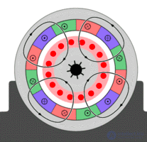
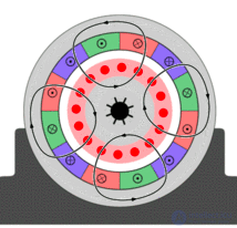
A three-phase alternating voltage is applied to the stator winding, under the action of which a three-phase system of currents flows through these windings. Since the windings of an induction machine are geometrically offset from one another by 120 degrees, and since in a symmetrical system the currents in the windings have a phase shift of 120 degrees, a rotating magnetic field is created in such windings. The rotating magnetic field, cutting across the conductors of the rotor winding, induces an electromotive force in them, under the action of which a current flows in the rotor winding; this current distorts the stator's magnetic field, increasing its energy, which leads to the appearance of an electromagnetic force under whose action the rotor begins to rotate (for a simpler explanation, one can refer to the Ampere force acting on the rotor winding conductors located in the stator's magnetic field; however, in reality, the magnitude of the magnetic flux density in the slot where the current-carrying conductor is located is quite small, since the magnetic flux passes mainly through the teeth). For an EMF to arise in the rotor winding, the rotor's speed of rotation must differ from the speed of rotation of the stator field. Therefore the rotor rotates asynchronously relative to the stator field, and the motor is called an induction (asynchronous) motor. The relative difference between the rotor's speed of rotation and the speed of rotation of the stator field is called slip (s). The rated slip is typically 2-8% .
When the stator winding is fed with three-phase (in the general case, polyphase) current, a rotating magnetic field is created, whose synchronous speed of rotation  [rpm] is related to the frequency of the supply voltage
  [Hz] by the relation:
 ,
,
where  — number of pole pairs of the stator winding.
Depending on the number of pole pairs, the following values of the stator magnetic field rotation frequency are possible, at a supply voltage frequency of 50 Hz:
| n, rpm | {\displaystyle p} |
|---|---|
| 3000 | 1 |
| 1500 | 2 |
| 1000 | 3 |
| 300 | 10 |
Most motors have 1-3 pole pairs, less often 4. A larger number of poles is used very rarely; such machines have low efficiency and power factor, but allow a gearbox to be avoided where a low rotational speed is needed. For example, there even exist 34-pole motors of type 2ASVO710L-34U1 (17 pole pairs) for driving cooling-tower fans (synchronous speed 176.5 rpm).
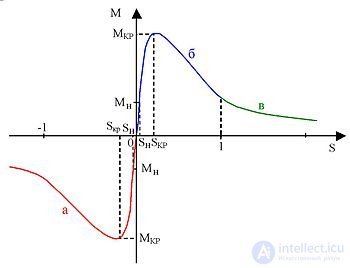
If the rotor is stationary or its rotational frequency is lower than the synchronous frequency, then the rotating magnetic field crosses the conductors of the rotor winding and induces an EMF in them, under the action of which a current arises in the rotor winding. Electromagnetic forces act on the current-carrying conductors of this winding (or, more precisely, on the teeth of the rotor core); their combined effect forms an electromagnetic torque, which drags the rotor along after the magnetic field. If this torque is sufficient to overcome friction forces, the rotor begins to rotate, and its steady-state rotational frequency {\displaystyle n_{2}} [rpm] corresponds to the electromagnetic torque being equal to the braking torque created by the load on the shaft, friction in the bearings, ventilation, etc. The rotor's rotational frequency cannot reach the rotational frequency of the magnetic field, because in that case the angular velocity of the magnetic field relative to the rotor winding would become zero, the magnetic field would stop inducing an EMF in the rotor winding and, in turn, stop creating torque; thus, for the motoring mode of operation of an induction machine, the following inequality holds:
 .
.
The relative difference between the rotational frequencies of the magnetic field and the rotor is called slip:
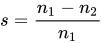 .
.
Obviously, in motoring mode  .
.
If the rotor is accelerated by an external torque (for example, by some motor) to a frequency higher than the rotational frequency of the magnetic field, then the direction of the EMF in the rotor winding and of the active component of the rotor current will change, i.e. the induction machine will switch to generator mode. At the same time the electromagnetic torque will also change direction, becoming a braking torque. In generator mode of operation, the slip {\displaystyle s<0} .
.
For an induction machine to operate in generator mode, a source of reactive power is required to create the magnetic field. In the absence of an initial magnetic field in the stator winding, the flux is created using permanent magnets, or, under an active load, by means of the machine's residual induction and capacitors connected in parallel to the phases of the stator winding.
An induction generator consumes reactive current and requires reactive-power generators to be present in the network, in the form of synchronous machines, synchronous compensators, or static capacitor banks (SCB). Because of this, despite its simplicity of maintenance, an induction generator is used comparatively rarely, mainly as low-power wind generators, small auxiliary power sources, and braking devices. The generator mode of an induction motor is used quite often in mechanisms with an active torque: motors of metro escalators can operate in this mode (when moving downward), when lowering a load in cranes, and elevator motors also operate in generator mode, depending on the ratio of the weight in the cabin and the counterweight; in this case, the braking mode of the mechanism required by the technology is combined with energy recovery into the grid, saving electricity.
operates without a load on the shaft, i.e., without a gearbox and a working member. From no-load test data, the values of the magnetizing current and the power losses in the core, bearings, and fan can be determined. In the real no-load mode s=0.01-0.08. In the ideal no-load mode n2=n1, hence s=0 (in reality this mode is unattainable, even assuming that bearing friction produces no load torque of its own — the very principle of operation of the motor requires the rotor to lag behind the stator field in order to produce the rotor's own field. At s=0 the stator field does not cut through the rotor windings and cannot induce current in them, meaning no rotor magnetic field is produced).
If the direction of rotation of the rotor or of the magnetic field is reversed so that they rotate in opposite directions, then the EMF and the active component of the current in the rotor winding will be directed the same way as in motoring mode, and the machine will draw active power from the mains. However, the electromagnetic torque will be directed opposite to the load torque, acting as a braking torque. The following inequalities hold for this mode:
 .
.
This mode is used only briefly, since it generates a large amount of heat in the rotor that the motor cannot dissipate, which can cause it to fail.
For gentler braking, generator (regenerative) mode can be used, but it is effective only at speeds close to rated speed.
Controlling an AC induction motor means changing the rotor speed and/or its torque.
There are the following methods of controlling an induction motor :
Russian scientists Fedyaeva G.A., Matyushkov S.Yu., Rogovets G.V. and Fedyaev N.A. proposed a method of operating traction induction motors with parallel connection to a single inverter. This method includes the calculated design of the current values of the electromagnetic torque and stator flux linkage in the DTC (Direct Torque Control) block for the first motor. The calculated measurement of the torque reference is carried out using a speed regulator employing signals of the higher or lower rotational speed of the induction motors connected in parallel. In traction mode, control is carried out according to the highest rotor speed. In braking mode, control is carried out according to the lowest rotational speed. The stator flux linkage reference ψs,ref is determined in the upper-level control system according to the relationship ψs,ref=f(ωavg), where ωavg is the locomotive speed referred to the motor shaft, or the average rotational speed of the motors. The technical result consisted in providing a high level of dynamic performance in motor torque control and the early detection and elimination of wheel slip and slide.
The invention relates to rail transport and can be used on rolling stock with traction induction motors (TIM) connected in parallel to a single autonomous voltage inverter (AVI). On locomotives, such parallel connection to a single inverter and joint control (regulation) of the TIMs is usually carried out within each bogie, which is why it is often called «per-bogie» control of the TIMs.
A known method exists for controlling two TIMs powered from a single inverter using vector control of the TIMs with constant rotor flux linkage. In this method, the state parameters of the motors are determined using sensors of the phase currents and rotational speed of each TIM, then, based on information about the rotational speed of the motors, a decision is made as to which motor should be used for control, and information about the stator current, flux linkage and rotor speed of that motor is used by the control system (CS) as feedback signals.
A drawback of this method is the presence of a large number of current sensors and the switching of all feedback loops depending on which motor is being used for control, which can lead to significant electromechanical oscillations and increased dynamic loads on the elements of the traction drive. Another drawback is control in traction mode based on the motor with the lower rotational speed, since in this case the necessary reduction of torque on the motor with the higher rotational speed is not carried out when adhesion conditions change abruptly (for example, running onto an oil spot). In addition, the drawbacks of this method also include the vector control of the TIMs itself, which requires direct and inverse coordinate transformations and compensation of cross-coupling feedbacks of the plant, which increase error and reduce the reliability of the system.
Also known is the Direct Torque Control system (DTC for short) (Kozyaruk A.E., Rudakov V.V. Direct torque control systems in frequency-controlled AC electric drives), which can be used to control TIMs.
A drawback of control methods using the DTC system is that they are designed for individual regulation of the motors (in particular, individual regulation of the TIM of each locomotive axle) and do not provide for the possibility of joint regulation of several TIMs connected in parallel to a single AVI.
Scientists Fedyaeva G.A., Tarasov A.N., Smorudova T.V. and Konokhov D.V. proposed a method for energy-efficient two-phase speed control of an induction electric drive with flexible power limitation. In the two-zone speed control method for an induction electric drive, the torque command limit calculated by the speed controller is determined by dividing the specified power by the motor's rotor rotational frequency, where the specified power value is determined depending on the temperature of the motor's stator winding, calculated from a model or measured by a temperature sensor, and the stator flux linkage command is determined in the first and second control zones from the torque command value based on a pre-calculated dependence of the stator flux linkage on motor torque, which provides the minimum stator current value for a given torque and has the shape of a saturation curve.
The invention relates to induction electric drives and can be used in industry and transportation in electric drive systems with direct torque control of induction motors.
A method of two-zone speed control of an induction electric drive with rotor flux weakening in a vector control system is known (Kozyaruk A.E., Rudakov V.V. Modern and prospective algorithmic support for frequency-controlled electric drives. - St. Petersburg: St. Petersburg Electrotechnical Company, 2004. - prototype). In this method, the flux linkage command block, in the first control zone (at motor speeds below rated), sets the rated value of the motor's rotor flux linkage. In the second control zone (at motor speeds above rated), field weakening (reduction of the magnetic flux relative to the rated value) is achieved by changing the rotor flux linkage command inversely proportional to the increase in rotational speed relative to the rated value. Minimization of the stator current can be achieved by maintaining equality of the stator current components.
The disadvantages of this method are the complexity and large volume of computation typical of vector systems, low disturbance rejection, the indirect effect on the rotor flux linkage through changes in stator current, the absence of flux linkage control of the motor in the first zone, and underutilization of the motor's power and heating capacity in the second zone.
Scientists Makarov L.N. and Izosimov D.B. proposed a method for optimal vector control of an induction motor
The invention relates to a controllable induction electric drive and can be used for controlling induction motors, in particular squirrel-cage motors, including traction motors. Specifically, the invention relates to induction drive systems in which the induction motor is powered from a controllable voltage or current source, for example an autonomous voltage or current inverter, a cycloconverter, etc. Such sources make it possible to realize any desired voltage (current) and supply frequency for the motor, with an accuracy possibly limited only by the high-frequency modulation component, and within the known limits of the converter's output current and voltage, determined by the power devices used.
There are known methods of vector control of induction motors in which the regulation of mechanical motion (electromagnetic torque) and the electromagnetic component (magnetic flux) are performed separately, by regulating the active and magnetizing components of the current vector, through corresponding shaping of the supply voltage. To implement vector control systems, information about the direction and magnitude of the magnetic field in the motor is required, for which, as a rule, models of the electromagnetic processes are used. Vector control systems usually use motor operating modes with a constant field, in which the parameters of the field model change only slightly; with constant rotor flux linkage, the magnetizing component of the current is constant, while the active component and the slip frequency are proportional to the electromagnetic torque.
The amount of heat released by a current-carrying electrical conductor depends on the resistance of the conductor and on the magnitude of the current flowing through it. Frequent switching-on and acceleration in the presence of a load torque create a very high thermal load on a squirrel-cage induction motor. The permissible heating of the motor depends on the temperature of the cooling medium (for example, air) around it and the thermal resistance of the winding insulation material.
The maximum permissible overheating of motors is regulated by dividing them into thermal (insulation) classes (formerly „insulation classes“) (IEC 60034).
A motor in its original thermal class must withstand continuous operation with the overheating caused by the rated power, without sustaining any damage. For example, at a cooling medium temperature of up to 40 °C, the maximum permissible overheating for thermal class 180(H)³ is 125 °C.
Torque induction motors are a special design of AC squirrel-cage motors. The rated parameters of these motors are calculated so that, even at a rotational speed of 0, the current drawn is as high as possible, but without causing thermal destruction.
This is useful, for example, for drives for door opening, point (switch) operation or press tools, which require the position to be reached and reliably held by means of the electric motor.
Another frequently used operating mode is the so-called plugging (counter-current braking) mode: An external load is able to turn the rotor against the direction of rotation of the field. The rotating field „brakes“ the rotational speed and draws generator energy from the system, which is fed back into the mains – almost rotational braking without the mechanical friction work of a brake.
SEW-EURODRIVE offers 12-pole torque induction motors DRM../DR2M.., which withstand prolonged overheating and are designed for use with the rated torque in the stopped state. SEW-EURODRIVE torque induction motors are suitable for various requirements and speeds and, depending on the operating mode, can have up to three levels of rated torque.
Explosion-proof AC motors
If electric motors are used in hazardous areas (in accordance with Directive 2014/34/EU; ATEX), certain protective measures must be taken for the drives. For this purpose, SEW-EURODRIVE offers various design options depending on the field and region of application.
For drive systems that operate directly from the mains and must additionally have a synchronous rotational speed, SEW-EURODRIVE offers the so-called motors LSPM. LSPM stands for Line Start Permanent Magnet. An LSPM motor is an AC induction motor with additional permanent magnets. It starts asynchronously, then synchronizes to the frequency of the supply voltage and thereafter operates in synchronous mode. This is a motor technology that opens up new, flexible application possibilities in drive engineering.
These compact hybrid motors have no rotor losses during operation and achieve an impressively high efficiency.
The energy-efficiency class achieved is up to IE4.
The frame size of the DR..J motor with LSPM technology is two sizes smaller than that of a standard motor of the same power and with the same efficiency. Motors of the same size achieve an energy-efficiency class twice as high as induction motors.

Comments