
Lecture
When current flows through a straight conductor, a magnetic field arises around it. The magnetic field lines of this field are arranged in concentric circles, at the center of which is the current-carrying conductor.
The direction of the magnetic field around a current-carrying conductor always corresponds strictly to the direction of the current flowing through the conductor. The direction of the magnetic field lines can be determined by the right-hand screw rule. The greater the current flowing through the conductor, the stronger the magnetic field that arises around it. When the direction of the current changes, the magnetic field also changes its direction.
As the distance from the conductor increases, the magnetic field lines become sparser. Consequently, the magnetic flux density and its field strength decrease. The maximum field strength Hmax occurs at the outer surface of the conductor. A magnetic field also arises inside the conductor, but its strength decreases linearly in the direction from the outer surface toward the axis. The magnetic flux density around and inside the conductor varies in the same way as the field strength.
If a straight current-carrying conductor creates a magnetic field, then the magnetic flux density at some point of this field is directly proportional to the current in this conductor, inversely proportional to the distance to the point at which the value of the flux density is considered, and also depends on the medium in which this conductor is located.
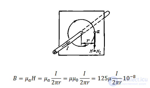
where B — is the magnetic flux density, T; I – is the current in the conductor, A; r — is the distance from the conductor to the point N at which the value of the magnetic flux density is considered; μa – is the quantity accounting for the magnetic properties of the medium, called the absolute magnetic permeability of the medium.
For vacuum, μa is denoted: μo= 4 π*10-7 H/m and is called the magnetic constant.
The quantity showing how many times the absolute magnetic permeability of a given medium exceeds the absolute magnetic permeability of vacuum is called magnetic permeability μ= μa / μo .
Depending on the value of magnetic permeability, all substances are, from a magnetic standpoint, divided into groups:
1) diamagnetic substances, for which – μ < 1 – these are Cu, Al, Zn, Ag, etc.
2) paramagnetic substances – with μ > 1 – these are air, Au, Pt…
3) ferromagnetic substances – with μ >> 1 and μ != const.
If the conductor is in a non-ferromagnetic medium, then, assuming μ=1, we obtain
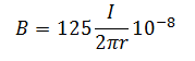
The formula given is valid for any value of r greater than the conductor's radius and for an infinitely long conductor; however, it is also applicable for a conductor of finite length if the distance r is much smaller than the length of the conductor and the point at which the flux density is determined is not near the end of the conductor.
Using Ampère's circuital law, it is easy to find the field strength inside a long cylindrical wire of radius a as well. At all points of the cross section of the wire, the current density
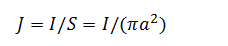
From symmetry considerations it follows that inside the wire, as well as outside it, all magnetic lines are concentric circles centered on the axis of the wire.
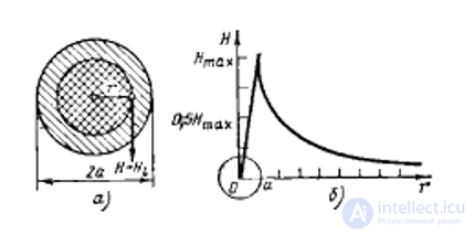
Fig. 2 Field strength inside a current-carrying wire (a) and distribution of field strength (b)
A circle of radius r<a centered on the axis of the wire represents a closed loop coinciding with a magnetic line. Denoting the cross-sectional area bounded by the closed loop,
 , and the current passing through this cross section,
  by Ampère's circuital law (1) we can write the expression for the magnetic field strength
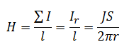
which is the same at all points of the loop and directed tangentially to the circle (Fig. 2,a), i.e., H=HL.
Substituting the expressions for current density and the area of the closed loop into the last formula, we obtain
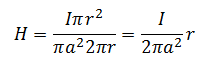
Thus, the field strength at an arbitrary point inside the wire is proportional to the distance r of that point from the axis of the wire. On the axis of the wire, H=0, since r=0. On the surface of the wire (r=a), the field strength has its maximum value:
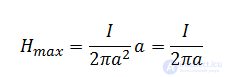
and further, for r>a, it decreases according to (2). The graph of the distribution of magnetic field strength inside and outside the conductor is given in Fig. 2, b.
The magnetic flux density inside the conductor equals the product of the magnetic field strength and the absolute magnetic permeability of the wire material, i.e.

where B — is the magnetic flux density, T; I — is the current, A; distances r and a — are in m.
To obtain strong magnetic fields with small currents, the number of current-carrying conductors is usually increased and they are formed into a series of turns; such a device is called a winding, or coil.
When a conductor is bent into the shape of a turn, the magnetic fields formed by all sections of this conductor will have the same direction inside the turn. Therefore, the intensity of the magnetic field inside the turn will be greater than around a straight conductor. When turns are combined into a coil, the magnetic fields created by the individual turns add up, and their field lines merge into a common magnetic flux. In this case, the concentration of field lines inside the coil increases, i.e., the magnetic field inside it is strengthened. The greater the current flowing through the coil and the more turns it has, the stronger the magnetic field produced by the coil. The magnetic field outside the coil is likewise made up of the magnetic fields of the individual turns, but the magnetic field lines are not as densely spaced there, so the field intensity there is not as great as inside the coil. The magnetic field of a current-carrying coil has the same shape as the field of a straight permanent magnet: the magnetic field lines emerge from one end of the coil and enter the other end. Therefore, a current-carrying coil constitutes an artificial electric magnet. Usually, to strengthen the magnetic field, a steel core is inserted inside the coil; such a device is called an electromagnet.
Electromagnets have found extremely widespread use in technology. They create the magnetic field needed for the operation of electrical machines, as well as the electrodynamic forces required. For the operation of various electrical measuring instruments and electrical apparatus.
Electromagnets can have an open or closed magnetic core. The polarity of the end of an electromagnet coil can be determined, just like the polarity of a permanent magnet, using a magnetic needle. It turns toward the north pole with its south end. To determine the direction of the magnetic field produced by a turn or coil, the right-hand screw rule can also be used. If the direction of rotation of the handle is aligned with the direction of the current in the turn or coil, the forward motion of the screw will indicate the direction of the magnetic field. The polarity of an electromagnet can also be determined using the right hand. To do this, the hand should be placed palm-down on the coil with the four fingers aligned with the direction of the current in it; the extended thumb will then indicate the direction of the magnetic field.
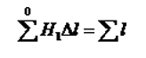
Let us use Ampere's circuital law to determine the magnetic field strength of a ring (toroidal) coil carrying current I, having w uniformly distributed turns (Fig. 7.19, a). To do this, we select a closed contour along the mean magnetic line of radius R. At every point of this contour, the magnetic field strength vector coincides with the tangent to the contour and has the same magnitude. Therefore the circulation of the field strength vector
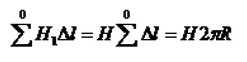
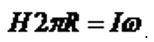
of the magnetic field along the closed contour, and the total current threading the surface bounded by the contour, ∑I=I. By Ampere's circuital law,
i.e.
. 
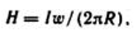
Consequently, the field strength of the coil along the mean magnetic line
and the magnetic flux density
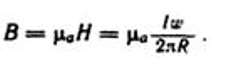
Similarly, the field strength and the magnetic flux density can be determined at all points of the circle of inner radius
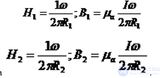
of the outer radius
.
A surface bounded by a contour whose radius is smaller than R1 (for example, radius R3) is not threaded by any current. Therefore, at points located on this circle, H=0 and B=0. A surface bounded by a contour whose radius is larger than R2 (for example, radius R4) is threaded by the current I in the forward and reverse directions ω times. Since the positive and negative currents cancel each other, the field strength and magnetic flux density at these points are equal to zero.
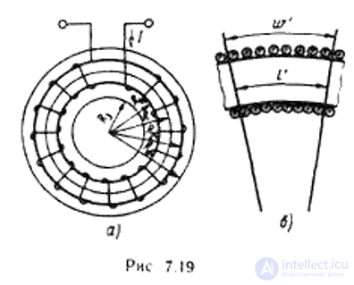
Thus, the magnetic field of a ring coil does not extend beyond its boundaries. At points located on the circle of the inner radius, the magnetic flux density reaches its maximum value, while at points on the circle of the outer radius — its minimum value. The average value of the magnetic flux density is determined from the formula derived for the mean radius R of the coil.
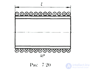
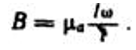
The magnetic field strength of a ring coil is numerically equal to the ratio of the magnetomotive force Iω to the total circumference length 2πR. The field strength can also be found in another way: by dividing the magnetomotive force Iω of part of the arc of the circle by the length of that arc l' (Fig. 7.19, b), i.e., H = Iω /l. A straight coil (Fig. 7.20) can be regarded as part of a ring coil with an infinitely large radius. Therefore, the magnetic field strength along the axial line of a straight coil, for a sufficiently large length, can be determined by the following approximate formula:
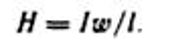
The error in determining H will be smaller, the larger the ratio of the coil's length to its diameter. The magnetic flux density of a straight coil

Comments