
Lecture
A logarithmic amplifier (log amp) is an electronic device that converts an input voltage into a corresponding output signal proportional to the logarithm of the input voltage.
A logarithmic amplifier (abbreviations: LA — in Russian-language literature, and Log amp — in English-language literature) — is a type of analog electronic amplifier whose output voltage is proportional to the logarithm of the input voltage.
LAs are often called logarithmic converters, since they convert the input signal nonlinearly (logarithmically).
The most important application of logarithmic amplifiers is compressing the dynamic range of signals that have a wide dynamic range. LAs are also used for multiplying and dividing analog signals.
When the input and output signals are voltage signals, the transfer characteristic of an LA has the following form:
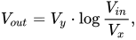
where  — is the output voltage,
 — is a certain constant coefficient, having the dimension of voltage,
 — is the input voltage,
 — is some voltage at which
In this formula, the choice of logarithm base is not essential, since logarithmic functions to any base are equal up to a constant multiplier; in this formula, the constant multiplier is the coefficient 
To uniquely determine the transfer characteristic of an LA given by this formula, two parameters must be specified — and
The specific implementation of a logarithmic amplifier can vary depending on the required characteristics and specifications. Operational amplifiers and various signal smoothing and filtering elements are typically used to implement logarithmic amplifiers.
It is important to note that the exact circuit and implementation of a logarithmic amplifier can depend on the specific application and the requirements for the device.
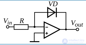
This LA makes use of the exponential dependence of the current through a semiconductor p-n junction diode. The dependence of the current through the diode  on the voltage across the diode
  according to the theory of the semiconductor p-n junction is expressed by the formula:
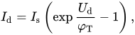
where  — is the thermal saturation current of the reverse-biased p-n junction,
 — is the thermal voltage.
The thermal voltage is expressed by the formula:

where  J/K — is the Boltzmann constant,
 — is the absolute temperature,
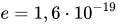 C — is the elementary charge.
At room temperature (~300 K), the thermal voltage is ~25,9 mV.
Since in practical circuits the voltage across the diode is several times greater than the thermal voltage, then 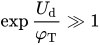 and the unity term in parentheses in the diode current formula can be neglected, therefore:
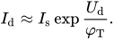
 since the potential of the inverting input of the operational amplifier (op-amp) is zero due to the action of negative feedback, and the diode current equals the input current, since the current into the inverting input is zero — these two assumptions hold for an ideal op-amp, and real op-amps approximate an ideal op-amp closely enough, that is
  the output voltage of the LA, whose circuit is shown in Figure 1, will be:

The «minus» sign in the formula indicates that this LA inverts the input signal.
Since the transfer characteristic formula includes two parameters that depend on the diode's temperature – — increases proportionally to absolute temperature, and  — for silicon diodes, approximately doubles for every 15 K increase in temperature; temperature changes cause a conversion error. In practical circuits, temperature drift is compensated by various circuit-design techniques, which complicates the circuit.
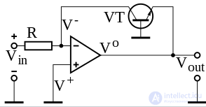
The drawback of the diode-based structure is a relatively narrow dynamic range, no more than 4 decades. It can be extended by using a bipolar transistor in the op-amp's feedback path. The dependence of the collector current of low-power silicon transistors on the collector-junction voltage follows an exponential law over a collector current range from units of picoamperes to a few milliamperes, which makes it possible to build log amps with a dynamic range of 5-6 decades.
The circuit of such a log amp is shown in Figure 2. For this circuit the following relations hold:

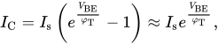
where  is the base-emitter voltage of the transistor,
is the reverse thermal saturation current of the emitter-base junction,
whence:
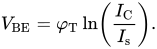
Because of the virtual ground at the op-amp's inverting input:

and finally:
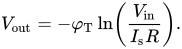
The transfer characteristic of this structure is also temperature-dependent, and for applications requiring increased accuracy, circuit-level compensation of the temperature drift is required.
The main application of logarithmic amplifiers relates to the processing of signals with a wide dynamic range, for example in audio and video equipment, telecommunication systems, radio communications, and other fields.
Logarithmic amplifiers can be used for various purposes, including amplitude compression (limiting the dynamic range), amplitude detection, and measuring and monitoring signals that have an exponential character of variation, for example acoustic or radio signals.
For measuring the transmitter power of signals in GSM, CDMA, TDMA systems, as well as for received signal strength indication (RSSI).
In measuring instruments, for example, in electrical signal spectrum analyzers.
For multiplying and dividing analog quantities represented by current or voltage. For this, the following identities are used:  and
and 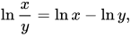 , whereby the operations of multiplication and division are replaced by operations of addition and subtraction, which are easily performed by analog summing amplifiers on op-amps. The conversion of the resulting logarithm of the product or quotient of the analog signals is then performed by an exponentiating (antilog) converter.
Logarithmic amplifiers are used in various ways, for example:
The reverse saturation current of a diode doubles for every ten-degree Celsius rise in temperature. Likewise, the emitter saturation current varies significantly from one transistor to another, as well as with temperature. Consequently, it is very difficult to establish a reference voltage for the circuit.

Comments