
Lecture
Capacitor motors are a type of induction motor whose windings include capacitors to create a phase shift in the current. They are connected to a single-phase mains by means of special circuits. By the number of stator phases, they are divided into two-phase and three-phase.
There are various connection schemes, with more options for three-phase motors, differing in the way the motor windings are connected and in the composition of additional elements, but the minimum workable circuit contains one capacitor, which is where the name comes from.
As a rule, one of the windings (the «motor phase») is powered directly from the single-phase mains, while the other windings are powered through an electrical capacitor, which shifts the phase of the applied current by almost +90°, or through an inductor, which shifts the phase by almost −90°. So that the resulting rotating magnetic field is not elliptical, a variable wire-wound resistor is connected in series with the capacitor, which is used to achieve a circular rotating magnetic field.
Industrial capacitor motors are, as a rule, based on a two-phase motor (simpler to manufacture and to wire). Three-phase motors are converted for a single-phase mains usually on an individual basis or in small-batch production, due to the mass availability of such motor and mains types, choosing in the process between circuit complexity and underutilization of the motor's power.
Such motors are used mainly in low-power household appliances: agitator-type washing machines, reel-to-reel and stationary cassette tape recorder mechanisms, inexpensive vinyl record players, fans, and other similar equipment.
Such motors are also used in circulation pumps of water-supply and heating systems (e.g., the Grundfos company), and in blowers and smoke exhausters of heating and water-heating units (e.g., Buderus).
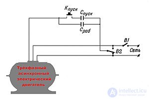
Three-phase induction motors are connected to a single-phase electrical mains through a phase-shifting capacitor.
The first lead of the motor winding is connected to the «phase» wire, the second lead — to the neutral wire. The third lead of the winding is connected through a capacitor whose capacitance is selected using formulas, depending on how the motor windings are connected — in wye or in delta.
If the windings are connected in wye, then the capacitance of the «working» capacitor should be
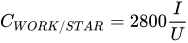 .
.
If the windings are connected in delta, then the capacitance of the «working» capacitor should be
 , where
 — mains voltage, volts;
 — motor operating current, amperes;
 — electrical capacitance, microfarads.
When the motor is started with the button, a starting capacitor  is connected, whose capacitance should be twice that of the working capacitor. As soon as the motor reaches the required speed, the «Start» button is released.
The switch  makes it possible to change the direction of rotation of the motor. The switch
  disconnects the motor.
Using the motor's nameplate data, its operating current can be determined by the formula:
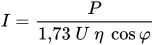 , where
 — electrical power of the motor, watts;
— mains voltage, volts;
 — efficiency;
 — power factor.
Practically the only way to implement an induction motor on an ordinary household single-phase mains.
The capacitance of the capacitor is selected for the case of the optimal rotational speed of the motor. If the rotational speed is lower than optimal (starting, or a large mechanical load, especially a variable one), the counter-EMF in the winding connected through the capacitor deviates from the ideal value, which unbalances the entire circuit and leads to the appearance of an elliptical magnetic field with a strong drop in power.
Therefore, the circuit is applicable only for small or practically constant loads, such as, for example, in a vinyl record player or a heating circulation pump. In a vacuum cleaner, for example, this is not possible, and therefore a commutator (brushed) motor is used there instead.
In addition, a capacitor motor, like any induction motor, imposes fairly high requirements on the quality of the sine wave and the frequency of the supply voltage. Therefore, devices containing such motors cannot be connected to a cheap «computer» UPS — in battery-operation mode the output of such a UPS is not a sine wave but a square wave, sometimes at a frequency significantly higher than 50 Hz. To power capacitor motors, a double-conversion UPS is desirable, one that synthesizes a sine wave with a proportion of high harmonics of less than 1/20.

Comments